Modbus Client and Server Devices
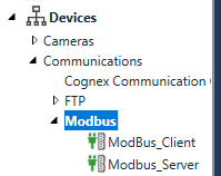
Modbus communication systems use Client and Server devices. (also called masters and slaves in other terminology). These clients and servers are represented as Devices in Cognex Designer.
Usually, Modbus Server Devices are measurement devices that measure and store data. On the other hand, Modbus Client Devices are usually supervisory systems used to monitor and control the Modbus Server devices. Modbus Client Devices periodically read (poll) and/or write data on the Modbus Server Devices: as such, communication is always initiated by a Modbus Client Device. It sends commands (Modbus Functions) to a Modbus Server Device which then sends back data as response.
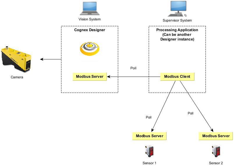
The example below illustrates a deployment where Cognex Designer acts as the Modbus Server . In this case, Cognex Designer runs as a vision system that measures data and provides the measured result to another system (that can be another installation of Cognex Designer).
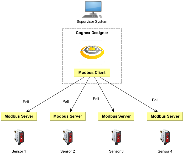
The example below illustrates a deployment where Cognex Designer acts as the Modbus Client. In this case, Cognex Designer is used to communicate with remote servers to acquire sensor data. Cognex Designer runs on a supervisor computer that periodically polls the sensors and processes and visualizes the data.
The Modbus TCP frame format used is as follows:
| Name | Length (bytes) | Description |
| Transaction ID | 2 | Used for synchronization between Client and Server messages. |
| Protocol ID | 2 | The value is zero for Modbus TCP. |
| Length field | 2 | The number of remaining bytes in the frame. |
| Unit identifier | 1 | Specifies the server address. The value is 255 if not used. |
| Function code | 1 | The function code that represents the Modbus operation (e.g. Read Coils = 1, Read Discrete Inputs = 2) |
| Data bytes | n | Data as response or commands, containing the address. |
The first four items are the communication overhead of the frame, while the last two items in bold are the payload of the message frame.