This topic contains the following sections.
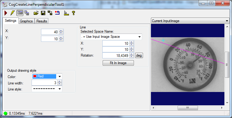
The Create Line Perpendicular edit control provides a graphical user interface to the CreateLinePerpendicular method, which creates a new line that is perpendicular to Line on the point (X, Y). The edit control allows you to configure the line and the point, dictate which graphics appear as the tool executes, and view tool results. The following figure shows the Create Line Perpendicular edit control:
The edit control offers the following features:
- A row of control buttons at the top left
- A set of function tabs to define the line and the point, choose what graphics the tool will use, and view results
- An image display window for displaying tool images and graphics
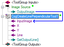
You can experiment with the edit control by using QuickBuild to create a CogCreateLinePerpendicular tool. A new CogCreateLinePerpendicular tool appears as shown in the following figure:
To include the edit control in your custom vision application, you must first add it to your Visual Studio.NET development environment. See Using Edit Controls in Your Custom Vision Applications for more information.

The following table describes the function of each button:
| Button | Description | Function |
 | Run | Creates a new line on the input point perpendicular to the input line |
 | Electric mode | Toggles electric mode, where the Create Line Perpendicular tool executes automatically when particular configuration parameters change. In electric mode, a lightning bolt appears next to every electric property |
 | Local image display | Opens or closes the local image display window. A Create Line Perpendicular tool supports the following image buffers:
|
 | Floating image display | Opens one or more floating image windows, which support the same image buffers as the local image display window |
 | Open | Opens a VisionPro persistence (.vpp) file that contains a set of saved properties for this vision tool object type. VisionPro reports an error if you try to open a .vpp file for another object type. |
 | Save | Saves the current properties of the vision tool to a VisionPro persistence (.vpp) file. The edit control allows you to choose between saving the vision tool with or without its image buffers and tool results. |
 | Save As | Saves the current properties of the vision tool to a new VisionPro persistence (.vpp) file |
 | Reset | Resets the vision tool to its default state. |
 | Show ToolTips | Enables or disables the display of tooltips for individual items in the edit control |
 | Help | Opens this VisionPro online help file |
Use the Settings tab to define the input point and input line. The following figure shows the Settings tab:
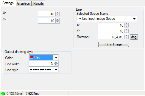
The Settings tab offers the following features for defining the point (X, Y):
| Feature | Description |
| X and Y | The (x, y) coordinate of the reference point on which the tool creates the perpendicular line |
The Settings tab offers the following features for defining Line:
| Feature | Description |
| SelectedSpaceName | Names the coordinate space for the line shape |
| X | The x-coordinate of the reference point on the line |
| Y | The y-coordinate of the reference point on the line |
| Rotation | The angle of the line |
| FitToImage | Centers the line within the Current.InputImage |
With the Output drawing style section, you can control the appearance of the output shape that is drawn on the image. See the controls and the example below.
| Feature | Description |
| OutputColor | The output shape color |
| OutputLineWidthInScreenPixels | The line width of the output shape |
| OutputLineStyle | The line style of the output shape |
Use the Graphics tab to control which graphics the Create Line Perpendicular tool generates and displays. The following figure shows the Graphics tab:
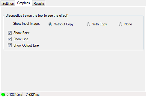
The Graphics tab offers the following features:
| Feature | Description |
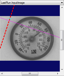
| Show Input Image | Determines whether or not the input image is recorded as part of the diagnostic record, and whether the image is copied to the record or saved in the record as a reference |
| Show Point | Show the input point in the LastRun.InputImage buffer |
| Show Line | Show the input line in the LastRun.InputImage buffer |
| Show Output Line | Show the line that runs through the input point and runs perpendicular to the input line |
Use the Results tab to view results of the perpendicular line that runs through the input point. The following figure shows the Results tab:
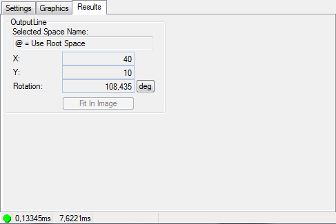
The Results tab offers the following features:
| Feature | Description |
| Selected Space Name | Names the coordinate space for the output image |
| X | The x-coordinate of the reference point for the line that runs perpendicular to Line |
| Y | The y-coordinate of the reference point for the line that runs perpendicular to Line |
| Rotation | The angle of the line |