This topic contains the following sections.
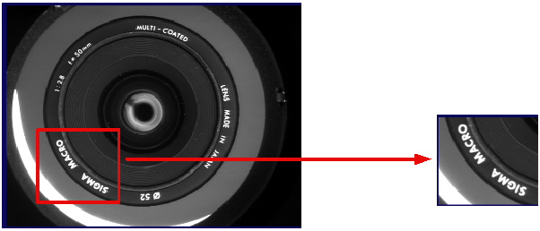
The process of transforming one image into another image begins by defining a region within a source image along with a description of how that region is to be transformed into a rectangular output image. For example, the simplest image transformation creates a new output image by specifying a rectangular section of an input image and the identity transform, as shown in the following figure:
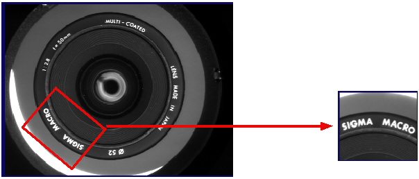
The transformation shown in the previous figure has a one-to-one correspondence between the pixels in the selected region and the pixels in the new image. Other transformations, however, are not so straightforward. For example, if you supply a rectangular input region that is rotated with respect to the pixels in the input image, it would not be possible to simply transcribe pixel values to create a rectangular output image with no rotation, as there is no correspondence between whole-pixel locations in the output image and whole pixel locations in the input image. The following figure shows an output image generated from a rotated input image:
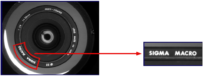
Other examples of transformations where there is no direct correspondence include a polar unwrap transformation, as shown in the following figure, and the nonlinear transformation generated by the Checkerboard Calibration tool.
The process of transforming an image can be divided into the following steps:
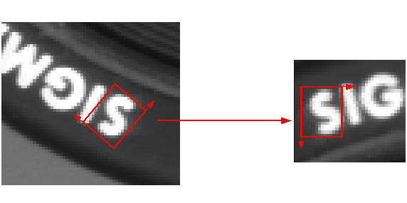
- Compute the mathematical transformation that maps the input region to the bounds of the output image. The particular transformation depends on the type of image
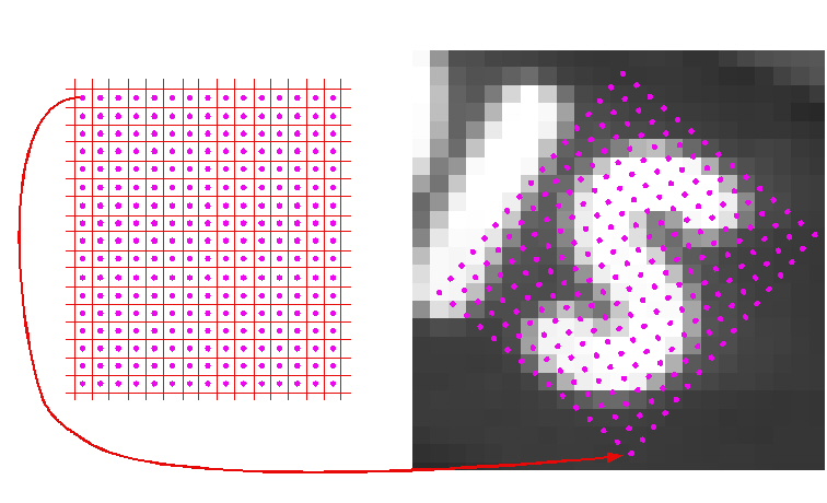
transformation you need to perform. The following figure shows an affine transformation that rotates a rectangular region in the input image to produce the output image:
- Use this transformation to map the center point of each pixel in the output image to its corresponding location within the input image. The red arrow in the following
figure shows the transformation of the center of the upper-left pixel in the output image to its corresponding location in the input image:
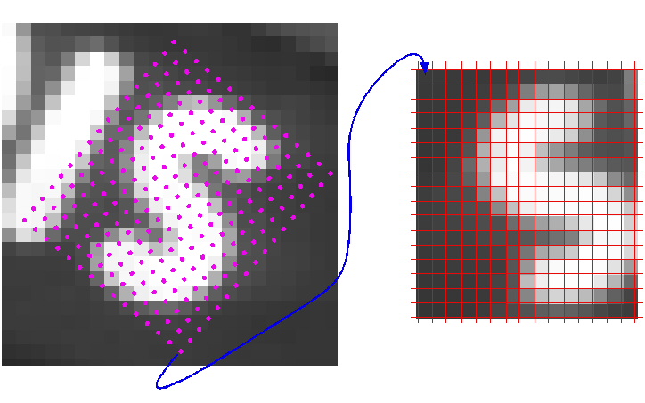
- Using one of the sampling methods described later in this topic, sample the pixel value in the input image at the transformed point and assign that value to the pixel
in the output image whose center was determined in the previous step.
The sampling method you choose to generate the output image determines the pixel values in the transformed output image. As shown in the following figure, the sampling points do not coincide with the pixels in the input image:
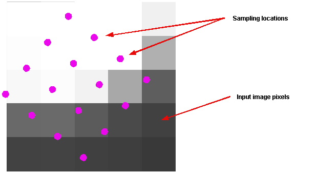
Vision tools that perform image transformation offer you a choice of sampling methods. You should experiment with the methods to determine which one offers you the best tradeoff between accuracy and execution speed.
Note: Not all tools support all sampling methods. The documentation for each image transformation tool lists the sampling methods that it supports.
The nearest neighbor sampling method, as illustrated in the following figure, uses the pixel value of the pixel whose center is closest to the sampling point as the value for the sampled pixel:
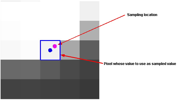
Nearest neighbor sampling executes faster than any other sampling method, but it does not produce the most accurate transformed images.
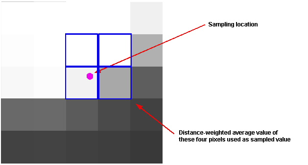
The bilinear interpolation sampling method computes the sampled value by taking the distance-weighted average of the values of the four pixels whose centers are closest to the sampling point, as shown in the following figure:
Bilinear interpolation produces a more accurate transformation than the nearest neighbor method, because it considers the values of more pixels in the input image. Bilinear interpolation uses the following formula to compute the sampled value:
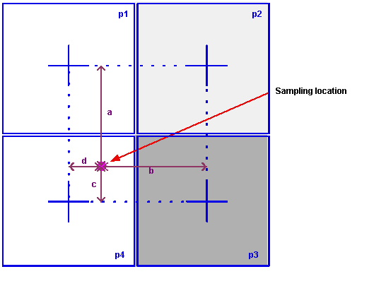
where a, b, c, and d are the four distances shown in the following figure, normalized so that the distance between pixel centers is 1, and p1, p2, p3, and p4 are the values of the four pixels shown in the following figure.
The high precision sampling method is similar to bilinear interpolation except that it considers additional pixels in determining the value of a sampled pixel.
In general, high-precision interpolation offers higher accuracy sampling than the bilinear interpolation method at a cost of slower execution speed.