This topic describes the Sobel Edge tool, which you use to analyze and enhance edge information in an image.
This topic contains the following sections.
| Term | Definition |
| edge | A change in the grey value of neighboring pixels, from dark to light or light to dark. |
| edge pixel | The pixel through which an edge passes. |
| edge angle | The orientation of an edge at an edge pixel, expressed as the angle between the x-axis of the selected space and a line drawn perpendicular to the edge going from dark to light. |
| edge angle image | Image created by replacing each pixel in an input image with a pixel whose grey value corresponds to the edge angle of that pixel. |
| edge magnitude | The magnitude of an edge, expressed as the difference between pixel values on the two sides of an edge. |
| edge magnitude image | Image created by replacing each pixel in an input image with a pixel whose grey value corresponds to the edge magnitude of that pixel. |
An edge is a boundary between two areas of pixels with different grey values, while an edge pixel is a pixel through which an edge passes. For example, the following figure shows a pixel grid over an image of an object under inspection:
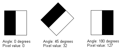
An edge in an image can be described by its magnitude, which is the amount of contrast between the two grey levels, and the angle, which is the angle between the x-axis and a ray drawn perpendicular to the edge going from the darker grey level to the lighter grey level.
For example, the following figure shows two triangles, with arrows whose lengths indicate the edge magnitudes and whose direction indicates the edge angles:
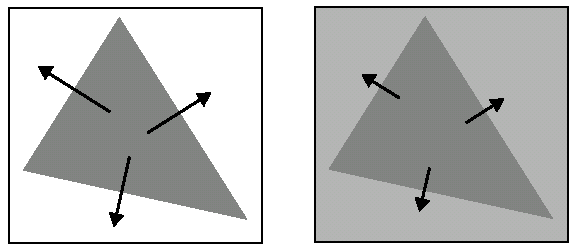
Both triangles have the same edge angles, but the edge magnitudes of the triangle on the left are greater than those of the triangle on the right due to the greater contrast between the feature and the background.
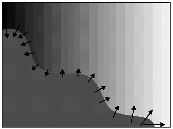
The magnitude and angle of an edge for any feature can change continuously. For example, the following figure shows a curved edge with varying edge magnitudes and edge pairs:
The edge magnitude and edge angle of a given pixel depend on the grey values of the eight surrounding pixels. The following figure shows a pixel, E, with its eight neighbors:
The Sobel Edge tool calculates the edge magnitude for the pixel E in both the x-axis and y-axis using the following formulas:
Using these separate magnitude measurements, the Sobel Edge tool calculates the overall edge magnitude for a pixel using the Pythagorean theorem:
In addition, the Sobel Edge tool calculates the edge angle according to the following equation:
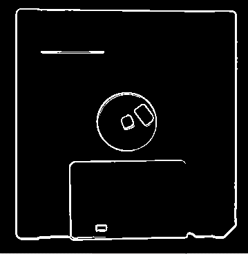
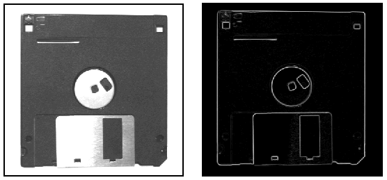
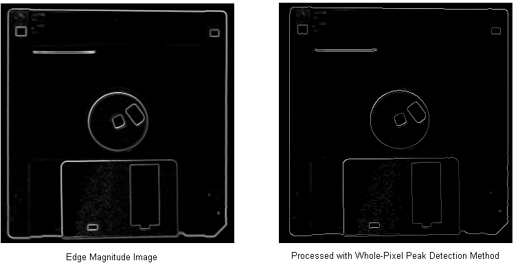
An edge magnitude image is an output image based upon the edge magnitude of the pixels in the input image. Edges with a large magnitude generate edges in the output image with lighter grey values, while edges with a smaller magnitude generate edges with darker grey values. For example, the following figure shows an input image of a diskette and the edge magnitude image it generates:
Like all grey-scale images, the pixels in an edge magnitude image can have grey values in the range 0 through 255. The formula for producing edge magnitude scores, however, can produce values greater than 255, up to a limit of 286. Since a pixel cannot store a grey value greater than 255, the Sobel Edge tool risks losing edge information for input images with strong edges.
To preserve accurate edge information, the Sobel Edge tool provides a magnitude scaling factor. The tool multiplies the grey value of each edge magnitude pixel by this scaling factor before adding it to the edge magnitude image. The tool uses a default scaling factor of 1.0, which causes no change to the pixels in the edge magnitude images but forces the tool to clip values greater than 255.
You can specify a lower scaling factor for high-contrast input images in order to accurately reflect all edges in your edge magnitude images. For example, use a scaling factor of .89 to ensure that no pixel value will exceed a grey level of 255 (286 * .89 = 255).
Specify a higher value for low-contrast input images if you need to expand the range of values in the edge magnitude image. Be aware, however, that using a value greater than 1.0 can cause some pixel values to exceed the limit of 255. The tool has a valid magnitude scaling factor range of 0.5 through 50.
An edge angle image is an output image based upon the edge angles of the pixels in the input image. The Sobel Edge tool expresses edge angles in pixel space, where an edge angle of 0 degrees indicates a dark-to-light edge perpendicular to the x-axis. Edge angles increase in the clockwise direction. Angle values from the input image are scaled to the range 0 through 255, and that value is used as the grey value for the pixel in the output image.
The following figure shows examples of different edge angles and the grey level results they would generate:
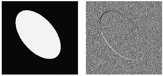
For pixels in the input image with no edge magnitude, the Sobel Edge tool fills the output image with random values. For example, the following figure shows an input image with varying edge angles and the output image it generates:
To further analyze an edge angle image, you might pass it to a Histogram tool to determine the number and value of any peaks. See the topic Passing an Edge Angle Image to a Histogram for more information.
When you use a Sobel Edge tool you can choose to apply it to an entire input image or only to a selected region of the input image. Applying the tool to the entire input image produces edge magnitude and edge angle images that are smaller by two pixels in both height and width.
Selecting a specific input region, meanwhile, affects the size of the output image depending on the number of edges the input region touches. For example, if your input region touches the left side of the underlying image, then the output image will be one pixel less in width than the width of the input region. If your input region touches the left side and the bottom of the underlying image, then the output image will be one pixel less in width and height when compared to the input region. Finally, if your input region lies entirely inside the underlying image, then the output image and the input region will have the same dimensions.
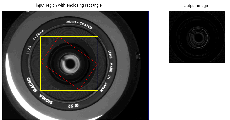
In addition, if you use a rotated region of the input image, then the size of the enclosing rectangle around the region determines the size of the output image, as shown in the following figure:
The edge magnitude image the Sobel Edge tool produces can be further processed using either of two post-processing operations. One operation refines the edge information in images where the edges span multiple pixels, while the other operation removes false edge information.
In addition to the edge angle image and edge magnitude images, the Sobel Edge tool produces a final magnitude image to reflect any post-processing operation you choose. If you choose not to apply either post-processing operation, the edge magnitude image and the final magnitude image are identical. Neither post-processing operation has any effect on the edge angle image.
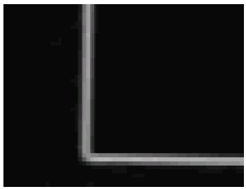
Edges within an edge magnitude image can span multiple pixels depending on factors such as the type of camera you use or the lighting in the production environment. For example, the following figure shows a magnified section of an edge magnitude image:
Using the whole-pixel peak detection method, the Sobel Edge tool can generate edge magnitude images with more precise edge information. The whole-pixel peak detection method considers a pixel to be a true edge if it has a greater magnitude value than both of the adjacent pixels that lie in the same direction within the image, and sets any non-edge pixels to 0.
For example, the following figure shows an edge magnitude image of a diskette and the same image further processed with the whole-pixel peak detection method:
If you choose to use the whole-pixel peak detection method, the Sobel Edge tool provides additional control over a peak detection threshold. While generating the final magnitude image, the tool will remove any pixel with a grey value below the threshold. You can set the value to 0 to prevent the tool from removing any pixels, or you can set it to a higher value when you know the edges of interest in your images have a high grey value.
Using the whole-pixel peak detection method enhances edge magnitude images so that the true edges can be isolated from misleading edge pixels, but it requires more processing time to generate the final magnitude image.
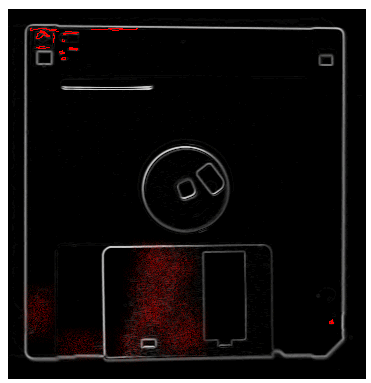
The whole-pixel peak detection method can be effective in altering edge magnitude images so that they provide more precise edge information, but it cannot eliminate pixels that represent video noise, light reflections, or other imperfections in the original image. Since the edges of interest in any image are usually represented by a collection of adjacent pixels, you can eliminate non-edge pixels using the process of edge hysteresis thresholding.
For example, the following figure shows an edge magnitude image of a diskette where non-edge pixels have been highlighted in red for visibility:
Edge hysteresis thresholding creates an image where all pixels have either an edge value or a non-edge value, so the first step in using the process is to select which grey value you want to represent edges and which value you want to represent everything else.
Next, you must select a low threshold and a high threshold for analyzing each pixel in the edge magnitude image. All pixels with edge magnitudes greater than or equal to the high threshold are automatically set to the edge value you assign, while all pixels with edge magnitudes lower than the low threshold are automatically set to the non-edge value you assign. Increasing the low threshold can be very effective in eliminating non-edge pixels, while setting the high threshold to a large value will eliminate all but the strongest magnitude values from the edge magnitude image.
Pixels with edge magnitudes greater than or equal to the low threshold must be connected to a pixel with a grey value greater than or equal to the high threshold, or be connected to a pixel with a value between the thresholds that is itself connected to a pixel with a grey value greater than or equal to the high threshold, in order to be given the edge value you assign.
Pixels with edge magnitudes greater than or equal to the low threshold but are not connected to, directly or indirectly, to a pixel with a grey value greater than or equal to the high threshold are assigned the none-edge value.
For example, the following figure shows the same edge magnitude image from the previous figure, but now the edge hysteresis thresholding process has been used to remove all of the non-edge pixels: