This topic contains the following sections.
This topic describes the Polar Unwrap tool, which warps the portion of an image contained within a circular annulus section or elliptical annulus section into a rectangular image.
The Polar Unwrap tool unwraps a circular or elliptical annular section of an image to create a rectangular image, as shown in the following figure:
A typical application for the Polar Unwrap tool is to create a rectilinear arrangement of features that are arranged radially in an input image.
The Polar Unwrap tool supports the following image types:
- 8-bit greyscale images (of type CogImage8Grey)
- 16-bit greyscale images (of type CogImage16Grey)
- Range images (of type CogImage16Range)
The Polar Unwrap tool is an image transformation tool. It works by following these steps:
- It constructs a transformation that maps a circular or elliptical annular section that you specify to the bounds of a rectangular output image.
- It uses this transformation to map the centers of the pixels in the output image to the corresponding points in the input image.
- It samples the pixel values in the input image at the transformed points to compute the pixel values in the output image.
Each of these steps is described in detail in the following sections.
You supply a CogCircularAnnulusSection or CogEllipticalAnnulusSection as the input region for the Polar Unwrap tool.
The tool unwraps the specified region of the input image so that the x-axis of the transformed image always corresponds to the angular direction of the region and the y-axis of the transformed image always corresponds to the radial direction of the region.
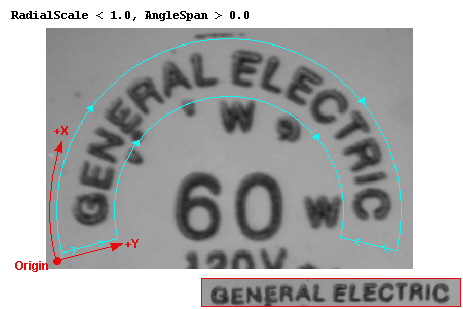
The values of the RadialScale and AngleSpan properties determine the relationship between the x-axis and y-axis in the output image and increasing and decreasing radius and angle in the input region. The following table summarizes how these parameters determine this relationship.
| Mode | Effect |
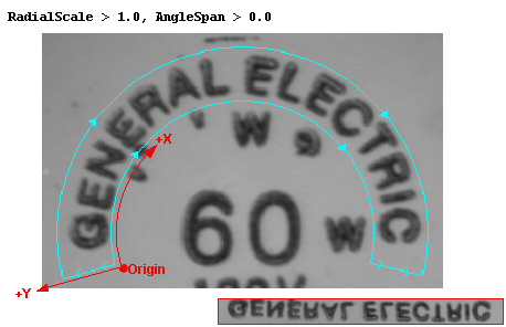 | X-axis values increase with increasing angle, Y-axis values increase with increasing radius. |
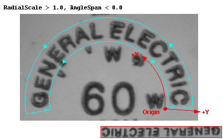 | X-axis values increase with decreasing angle, Y-axis values increase with increasing radius. |
 | X-axis values increase with increasing angle, Y-axis values increase with decreasing radius. |
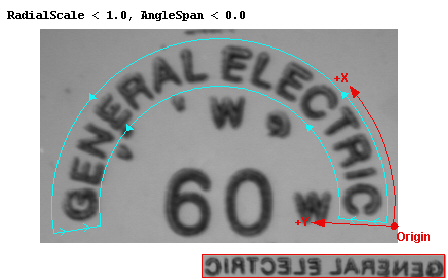 | X-axis values increase with decreasing angle, Y-axis values increase with decreasing radius. |
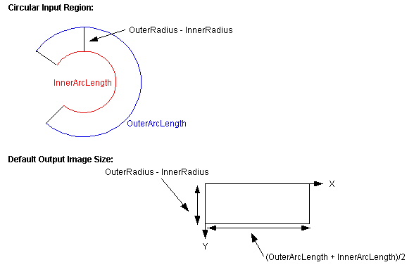
The number of sampled points in the input region determines the size of the output image in pixels. The Polar Unwrap tool automatically computes the size of the output image so that the image distortion is minimized. For a circular input region, the default x-axis size is the average of the inner and outer arc lengths while the default y-axis size is the difference between the inner and outer radii, as shown in the following figure:
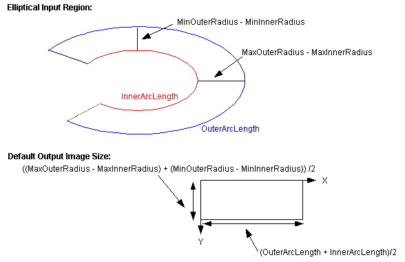
For an elliptical input region, the default x-axis size is the average of the inner and outer arc lengths while the default y-axis size is the average of the differences between the largest and smallest inner and outer radii, as shown in the following figure:
You can specify a different output image size by supplying values for the ScalingX and ScalingY properties. The tool multiplies the computed output image dimension by the values you specify for these scaling factors.
The Polar Unwrap tool supports both nearest neighbor sampling and bilinear interpolation.
This section describes some aspects of using the Polar Unwrap Tool.
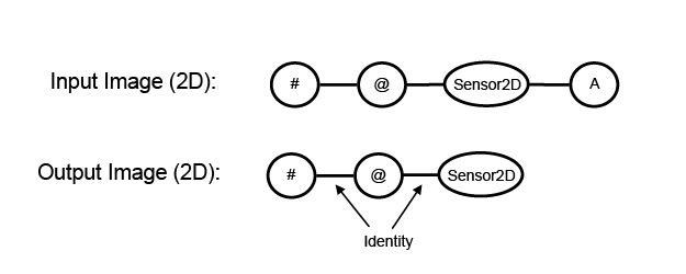
When you run the Polar Unwrap tool on an 8-bit or 16-bit greyscale image, the tool computes a highly nonlinear transformation that maps the specified input region to a rectangular output image. The tool does not add this transformation to the coordinate space tree of the output image. You should regard the tool's output image as a newly acquired image. Its currently selected space is always root ("@") space, and the transformation between the image's pixel space ("#") and root space is always the identity transformation.
The Polar Unwrap tool does not make this nonlinear transformation available to you directly. You can, however, map individual points from the output image to the input image and back using the GetInputPointFromOutputPoint and GetOutputPointFromInputPoint methods.
During unwrapping a range image, both the height data and the Visible Pixel Mask are unwrapped.
A range image contains both a tree of 2D coordinate spaces and a tree of 3D coordinate spaces. In the case of range images as well, we treat the polar unwrap output as a newly-acquired image from a "polar" 3D camera. The range images produced by this 3D camera have a Sensor3D space (in the 3D tree) and a Sensor2D space (in the 2D tree) just like any range image produced directly by a DS unit. The meaning of these spaces, however, is different from the meaning of the spaces in any range image acquired by a DS unit.- Sensor2D is exactly equivalent to the 2D "@" space (and 2D "#" space) of the output range image. This choice matches the behavior of polar unwrap when used on 8-bit or 16-bit grey images, but for range images it changes Sensor2D space from millimeters (in the input image) to pixels (in the output image). It also changes the handedness of Sensor2D from right-handed (in the input image) to left-handed (in the output image). The differences between the 2D coordinate spaces of the input range image and the 2D coordinate spaces of the output range image are shown in the following image:
-
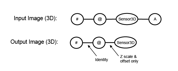
Sensor3D of the output range image is exactly equivalent to Sensor2D in the image X and Y dimensions. In the Z dimension, however, Sensor3D retains whatever scaling and offset was present along the image-Z direction of the input image's 3D selected space. The scaling value will always be positive: larger pel values in the output range image will always be interpreted as having larger Z values in the Sensor3D space of that range image. The differences between the 3D coordinate spaces of the input range image and the 3D coordinate spaces of the output range image are shown in the following image:
// Declare useful variables.
Double pointInSSNOfInputImageX, pointInSSNOfInputImageY;
Double pointInPelsOfInputImageX, pointInPelsOfInputImageY;

// Extract input and output range images from polar unwrap tool.
CogImage16Range mInImg = (CogImage16Range) mTool.InputImage;
CogImage16Range mOutImg = (CogImage16Range) mTool.OutputImage;

// Map (60, 210, 48) to the "#" space of the output image...
Cog3DVect3 pointInPelsOfOutputImage =
    mOutImg.GetTransform3D("#", "Sensor3D")
                  .MapPoint(new Cog3DVect3(60, 210, 48));

// Now map the X & Y "#" space coordinates to the 2D
// SelectedSpaceName of the input range image...
mTool.RunParams.GetInputPointFromOutputPoint(
    mTool.InputImage, mTool.Region,
    pointInPelsOfOutputImage.X, pointInPelsOfOutputImage.Y,
    out pointInSSNOfInputImageX, out pointInSSNOfInputImageY);

// Map the 2D result to the "#" space of the input range image...
mInImg.GetTransform("#", mInImg.SelectedSpaceName).MapPoint(
    pointInSSNOfInputImageX, pointInSSNOfInputImageY,
    out pointInPelsOfInputImageX, out pointInPelsOfInputImageY);

// Finally, map the full 3D point from "#" space of the input
// range image to the SelectedSpaceName3D of the input range image.
// When creating the 3D point we use the "#" space Z value from
// the output range image because we know that it is the same as
// the "#" space Z value in the input range image.
Cog3DVect3 pointInSSN3DOfInputImage = mInImg
    .GetTransform3D(mInImg.SelectedSpaceName3D, "#")
    .MapPoint(new Cog3DVect3(pointInPelsOfInputImageX,
                             pointInPelsOfInputImageY,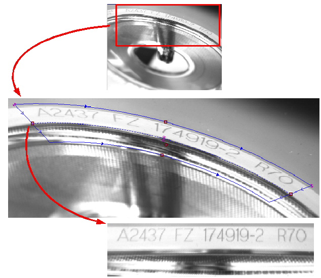
pointInPelsOfOutputImage.Z));The Polar Unwrap tool lets you use either a circular or an elliptical annular section as its input region. A common use for an elliptical annular section is to unwrap features from a circular object that was at an angle when the image was acquired, as shown in the following figure:
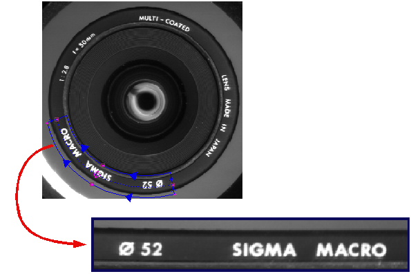
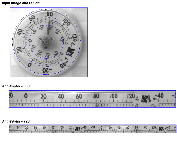
The Polar Unwrap tool lets you unwrap more than an entire circle. You do this by specifying an angle span of greater than 360° or less than –360°. One application for this is unwrapping text strings where you do not know the orientation of the object in advance. By unwrapping 720°, you can ensure that you acquire a contiguous copy of the entire string.
The following figure shows how you can use a larger angle span to ensure that a complete copy of a text string is included in the output image:
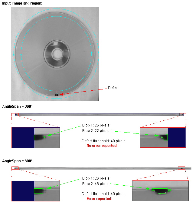
Another common application is detecting defects in circular objects where the orientation of the object is not known. If you only unwrap 360° of the object, there is a chance that a defect could be missed if it lies at one end of the output image. By unwrapping an extra 10° to 30°, you can ensure that regardless of the position of the defect, it will be present in the output image.
The following figure shows how an application that uses the Blob tool to measure defects based on area could fail if an AngleSpan of 360° is specified when the defect falls at the start or end of the angle range. By increasing the angle span to 380°, the defect is no longer missed: