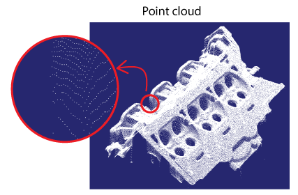
VisionPro supports 3D area scan sensors that return point clouds - sets of 3D points that represent the surface of one or more objects in some three-dimensional coordinate system. The following figure shows a 3D representation of a point cloud and highlights individual points in the data structure:
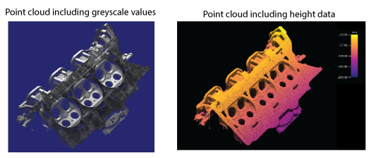
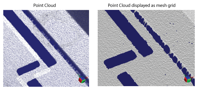
Point clouds can be displayed to represent the greyscale value of objects under the sensor, or the height data of features it detects:
See the following sections for more information:
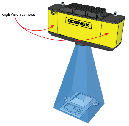
VisionPro supports the 3D-A5000 series of sensors to perform 3D area scans and generate point clouds. Cognex 3D-A5000 series sensors combine structured light projection and GigE Vision cameras to generate information about three-dimensional objects that cannot be easily generated by cameras that acquire two-dimensional images. To acquire a point cloud, the sensor projects a pattern on an area within the field of view of both enclosed GigE Vision cameras:
Cognex software builds a 3D point cloud from the geometrically distorted images taken from the two cameras, which can then be viewed dynamically through a 3D viewing option. Be aware most VisionPro tools display a point cloud as a mesh grid, not as individual points:
For more information about the 3D-A5000 series sensors, refer to the 3D-A5000 Series Sensors Hardware Reference, installed with your VisionPro installation or available from the VisionPro Support site.
See the following sections for important details about using a 3D-A5000:
- 3D Range and Greyscale Images
- Image Options
- GigE Vision Configuration Tool
- Windows 10 Network Parameters
VisionPro stores acquired point clouds in objects of type Cog3DPointCloudMesh. Be aware that in addition to point clouds, a 3D-A5000 sensor can acquire other data types:
CogImage16Range 3D range images
See the topic Working with 3D Range Images for more information about 3D range images.
CogVisionDataContainer containing a 3D range image and 16-bit greyscale data
Vision tools such as the Cog3DVisionDataStitch tool and Cog3DVisionDataRerender tool accept a CogVisionDataContainer.
CogImage8Grey 2D greyscale intensity images.
Most VisionPro vision tools can analyze a 2D greyscale image.
VisionPro offers a variety of options when acquiring images with a 3D-A5000, and produces an ICogVisionData with contents depending on the specific acquisition mode you choose.
| Option | CogVisionDataContainer Containing |
| point_cloud | A Cog3DPointCloudMesh object containing a point cloud |
| point_cloud_with_grey |
A point cloud with grey intensity image, which returns the following image types:
|
| point_cloud_with_range |
A point cloud with range image, which returns the following image types:
|
| range_image | A CogImage16Range 3D range image |
| range_with_grey | A CogImage16Range 3D RangeWithGrey image |
| grey_image_primary | A CogImage8Grey image from the left (primary) GigE Vision camera as viewed from the front of the 3D-A5000 sensor. |
| grey_image_secondary | A CogImage8Grey image from the right (secondary) GigE Vision camera as viewed from the front of the 3D-A5000 sensor. |
Before you can analyze any point cloud or 3D range image data captured by the sensor, you must separate the ICogVisionData using a Cog3DA5000VDCSplitterScript toolblock, which accepts the output from a CogAcqFifoTool and makes the component data available as individual image types, as shown:
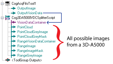
See the section Using QuickBuild for more details on the flow of vision tools when using a 3D-A5000 sensor.
Before you can use your 3D-A5000 sensor, it must be configured with a valid IP address related to the 10Gb Ethernet adapter installed in your computer.
Launch the Cognex GigE Vision Configuration Tool to assign the 3D-A5000 with a valid IP address. The tool displays all the network connections that correspond to the network adapters in your computer and any GigE Vision cameras connected to them.
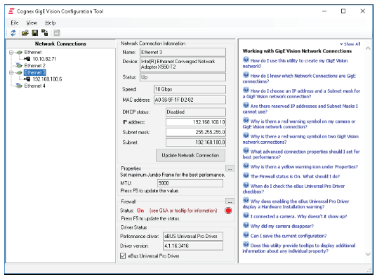
The tool supports a set of Questions and Answers for user assistance.
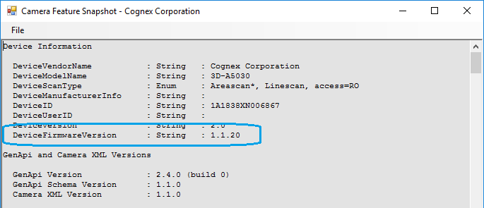
Use the Show Feature Snapshot button to view the current firmware of the 3D-A5000 sensor:
Cognex strongly recommends you use the Windows 10 Network and Sharing Center and assign specific settings to certain network parameters:
- Open the Windows 10 Network and Sharing Center.
- Click Change adapter settings.
- Right-click on the network connection corresponding to your 10Gb Ethernet adapter you are using with your 3D-A5000 and choose Properties.
- Under the Networking tab, click Configure.
- Click the Advanced tab.
Set the following parameters to these settings:
- Jumbo Packet: 9014 bytes
- Interrupt moderation: Off
- Maximum Number of RSS queues: 16
- RX Ethernet Queue Size: 4096
- RX Offload Queue Size: 2048
- TX Ethernet Queue Size: 4096
- TX Offload Queue Size: 4096
The 3D-A5000 sensor supports a set of custom properties that control acquisition parameters such as an exposure time, a region of interest, and more.
VisionPro supports the CogAcqCustomProperty class for programmatic access to the properties, and the AcqFifoTool Edit Control for modifying the properties through QuickBuild. See the topic Custom Properties for details.
For many new 3D applications, Cognex recommends you use the A5000 Viewer to determine and set which acquisition parameters work best for the object you want to analyze. The Viewer supports a graphical user interface that can make it easier to configure the acquisition properties of a 3D-A5000 sensor.
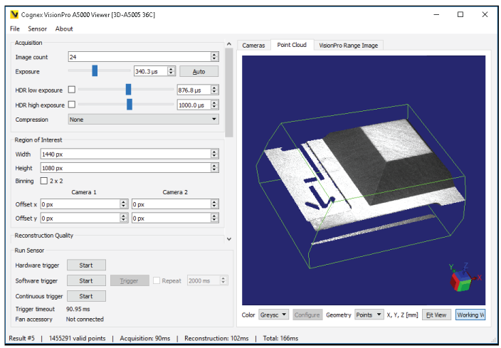
Any configuration you save in the A5000 Viewer are passed to QuickBuild and/or your Visual Studio application automatically.
Launch the A5000 Viewer by double-clicking the icon your VisionPro installation installs on your desktop:

See the topic The A5000 Viewer for details on using the A5000 Viewer.
Perform the following steps to use QuickBuild and acquire images from the 3D-A5000 sensor:
(Optional) Use the A5000 Viewer to configure acquisition parameters for the 3D sensor.
You do not have to use the Viewer if you choose to set all the acquisition parameters in the CogAcqFifoTool API or AcqFifoTool Edit Control, but the A5000 Viewer offers convenient access to many parameters and you can test the results of parameter changes quickly on the images the sensor can acquire.
Save your A5000 Viewer configuration to automatically pass the settings you choose to QuickBuild or the VisionPro API.
- Launch QuickBuild and open your CogJob.
Select Configure->Job Properties and clear the Acquire Images from Image Source checkbox:
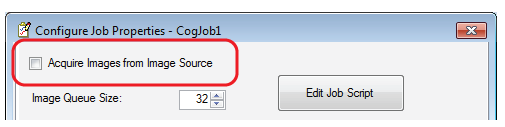
The default Image Source for a QuickBuild CogJob cannot expose the necessary parameters for working with point clouds.
Close the Job Properties window.
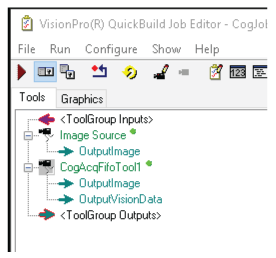
- Open the QuickBuild toolbox and add a CogAcqFifoTool to the CogJob:
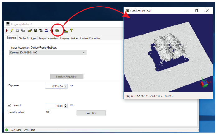
- Open the CogAcqFifoTool edit control and select the 3D-A5000 as an Image Acquisition Device:
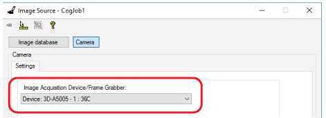
Select the Custom Properties tab and select the acquisition_mode property:
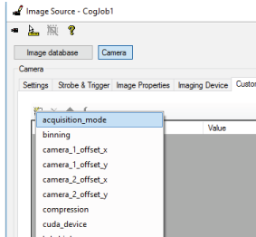
Select the type of data you want to capture from the sensor. See the section Image Options for a list of all the options.
- Add a Cog3DA5000VDCSplitterScript toolblock and link the OutputVisionData from the CogAcqFifoTool to the toolblock:
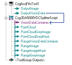
- Pass the desired output terminals from the Cog3DA5000VDCSplitterScript toolblock to other vision tools as necessary for your vision application.
VisionPro supports several methods of viewing the point clouds you acquire with a 3D-A5000:
The AcqFifoTool Edit Control and the 3D PatMax Edit Control both support viewing acquired point clouds.
The AcqFifoTool Edit Control supports a 3D Display window option that will display acquired point clouds:
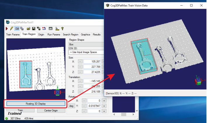
The 3D PatMax Edit Control supports a floating 3D display to allow you to define a train region and search region:
Use a Cog3DDisplayV2 control in your Visual Studio applications to visualize the point clouds that your application acquires. Be aware that VisionPro also supports the Cog3DDisplayV2WF Windows Forms version of the control that supports the same functionality.
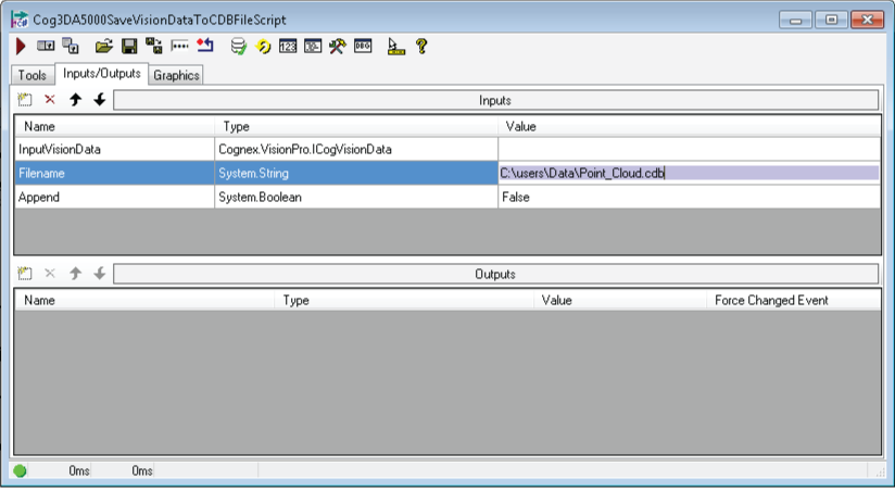
VisionPro offers a method to save image data acquired through a 3D-A5000 in an image-database file, and to load data stored in an image-database file for use in your vision application.
Use the following CogToolBlocks to save and load the image data acquired using a 3D-A5000 into a vision application:
- Cog3DA5000SaveVisionDataToCDBFileScript
- Cog3DA5000LoadVisionDataFromCDBFileScript
Configure the Filename terminal on the Input/Outputs tab with the location and name of the file to save/load the image data: