The 3D-A5000 sensor supports a set of custom properties that control acquisition parameters such as an exposure time, a region of interest, and more.
For many new 3D applications, Cognex recommends you use the A5000 Viewer to determine and set which acquisition parameters work best for your 3D-A5000 sensor. The Viewer supports a graphical user interface that can make it easier to configure the acquisition properties of a 3D-A5000 sensor, and VisionPro can pass the settings you choose to QuickBuild and/or your Visual Studio application automatically.
See the topic Custom Properties for details on modifying the custom properties using QuickBuild or programatically.
See the following sections for more information:
Launch the A5000 Viewer through the Start menu or double-click its icon on the Windows desktop:

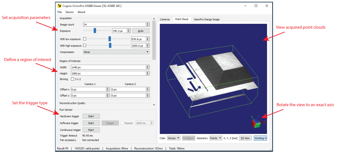
The Viewer offers a single panel for configuring many acquisition settings and viewing their impact on the cloud points you acquire:
Be aware a 3D-A5000 sensor must have a configured IP address relative to the GigE Vision network adapter installed in your computer. Without the IP address VisionPro (including the A5000 Viewer) cannot communicate with the sensor. See the section GigE Vision Configuration Tool for more information.
Use the File menu to connect the application to a connected 3D-A5000 sensor.
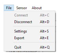
| Connect (or Alt+C) | Connect the A5000 Viewer to the listed 3D-A5000 sensor. |
| Disconnect (or Alt+D) | The Viewer prompts you to save any unsaved settings when you disconnect. |
| Export (or Alt+E) | For each image acquisition, the Viewer offers you the ability to save each point cloud and/or the 2D intensity images from the separate GigE Vision cameras. Configure the following settings for saving the images:
|
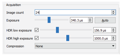
| Image count | Specify the of images used for 3D-reconstruction for each image acquisition
|
| Exposure | Choose an exposure time for each 2D image, in microseconds
|
| High Dynamic Range (HDR) settings | Enable the High Dynamic Range (HDR) exposure settings in applications where your production environment can cause dark shadows and bright glare over the object being inspected. Enabling one of these makes the sensor acquire an additional sequence with another exposure time to use for reconstruction.
Be aware of the following when using HDR exposure settings:
|
| Compression | Enable Low Compression to perform 10-bit acquisition and capture a larger dynamic range of pixel values. Be aware that Compression requires approximately a 4x longer exposure to take advantage of the larger dynamic range.
Use Compression as an alternative to using low and/or high HDR exposure settings. Compression has less impact on acquisition time but the results might not be as precise. |
You can specify a smaller camera resolution to limit the size of the image as required by your vision application. For example, if the object under inspection is significantly smaller than the default field of view for the sensor, acquisition and processing speeds will generally increase as you specify smaller parameters for the width, height and offset of your 3D range image.
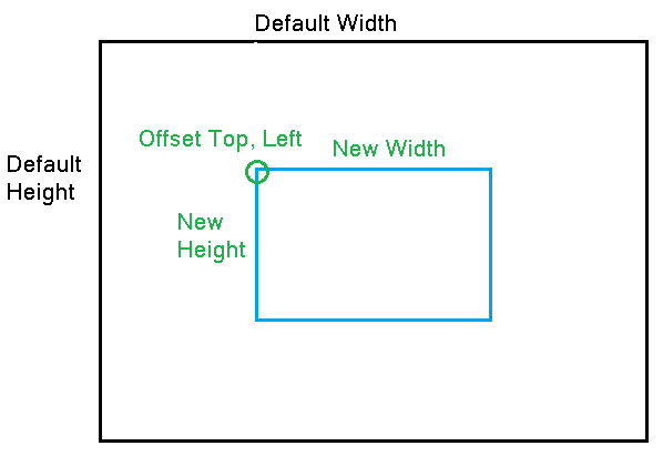
Use the following parameters to set the region of interest:
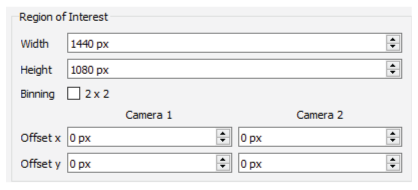
| Width | Image resolution along the x-axis Valid values between 80 and 1440, by increments of 8 |
| Height | Image resolution along the y-axis Valid values between 4 and 1080, by increments of 4 |
| 2 x 2 Binning | Combines 2 x 2 matrices of pixels into one pixel, generating significantly brighter images compared to those without 2 x 2 Binning enabled. 2 x 2 Binning offers the following benefits:
|
| Offset x and Offset y | Use Offset values to move the region of interest for either GigE Vision camera:
|
Choose a Reconstruction Quality control to choose a value between 0 (lowest quality, lowest reconstruction time) and 9 (highest quality, highest reconstruction time).
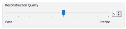
Experiment with this parameter for best results.
Choose a Pre-Filtering value applied to the GigE Vision cameras before reconstruction:
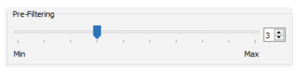
- Choose a value between 0 (minimum filter intensity) and 9 (maximum filter intensity).
- The higher the setting, the lower the reconstruction time.
- Pre-filtering removes noisy data such areas of the image that are overexposed, underexposed, or show low-pattern visibility
Choose Post-Filtering values to control the amount of data in the 3D reconstruction:
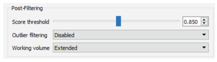
| Score threshold | Enter a minimum quality score each 3D point has to exceed before it will be included in the output 3D range image. Increasing this value will lead to fewer outliers being included in the final 3D range image but will increase the number of missing points. Cognex recommends a value of at least 0.7 and typically below 0.95 for most applications. |
| Outlier filtering | The options are Disabled, Permissive, Balanced and Strict, in that order. As you increase the policy from one to the next, the number of outliers included in the 3D range image decrease while increasing the risk of filtering out valid 3D points. |
| Working volume | Define the volume of space within the field of view of both GigE Vision cameras in which 3D points will be constructed:
Click Show Working Volume to toggle the view of the working volume in the 3D display. |
By default the 3D sensor generates a 3D range image from all data within the field of view of both cameras. Enable a Volume of Interest and use the values X limits, Y limits and Z limits to extract a portion of the available 3D object volume. The settings allow you configure the smallest and highest limits for each axis.
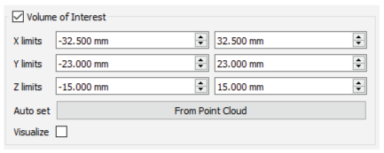
Click From Point Cloud to limit the volume of interest for future image acquisitions based on the content of the current 3D reconstruction.
Click Visualize to enable a blue wire-frame box to represent the volume of interest in the 3D Viewer window.
Configure the application to use a software trigger through the Viewer interface or a hardware trigger in response to a signal over the hardware trigger line.
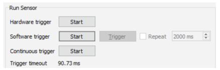
Be aware you must click Start before the application responds to any trigger events. Click Stop to prevent the application from responding to trigger events.
| Hardware trigger | The application responds to a signal received over the hardware trigger line. For more information on hardware triggers, refer to the 3D-A5000 Series Sensors Hardware Reference, installed with your VisionPro installation or available from the VisionPro Support site. |
| Software trigger | The application performs an image acquisition each time you press Trigger. Enable the Repeat checkbox repeat software trigger events at an interval you specify, in milliseconds (ms). |
| Continuous trigger | The application acquires images continuously without responding to trigger events (software or hardware). Continuous mode provides the highest possible rate of 3D image acquisitions. |
The Viewer also displays a Trigger timeout to represent the minimum duration the 3D-A5000 requires between triggers (software or hardware).
View each image acquisition in the 3D viewport:
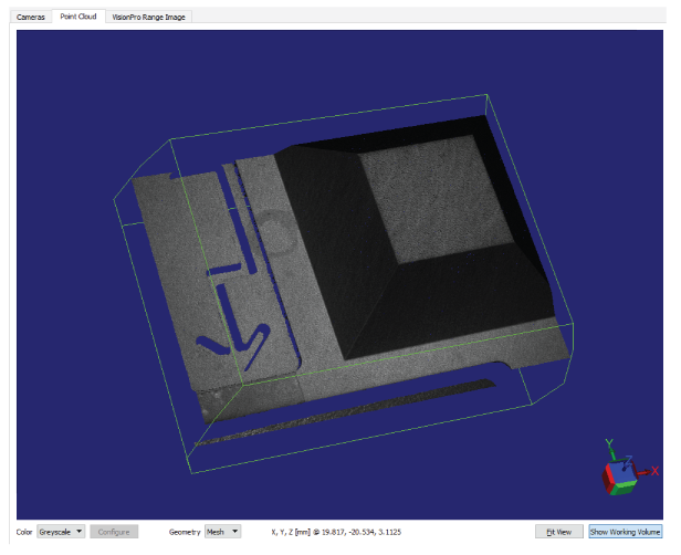
Left-click and drag the mouse inside the viewport to rotate the image. Click on a single face of the axis cube at the bottom-right to snap the view to that axis.
See the following sections for more information on using the Viewport:
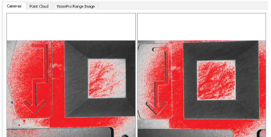
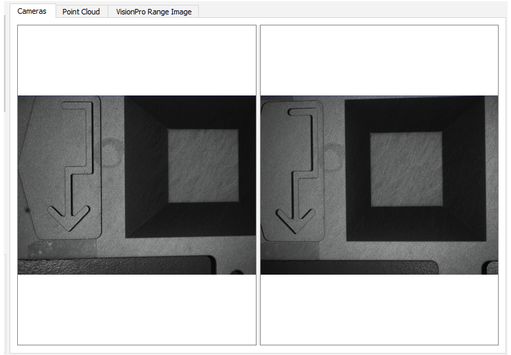
The tabs along the top of the 3D viewport allow you to view the 2D intensity images used to create the point cloud, the point cloud itself, or the 3D range image calculated from the point cloud. The following figure shows the 2D intensity images from the latest acquisition:
Use the Color pulldown menu to choose how to view the point cloud:
- Greyscale: View the point cloud with an overlay of the grey values from the GigE Vision cameras.
- Height: View the point cloud in color representing the height of features in the image.
Click Configure to determine if the viewport assigns colors automatically or displays colors based on a range of Z values:
Click From Point Cloud to let the viewport assign a range of colors based on the volume of the point cloud along the z-axis.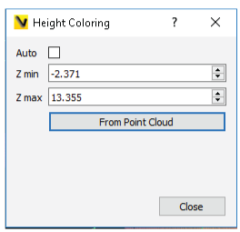
- None: View the point cloud with no greyscale overlay.
Choose between Mesh or Points for how the viewport displays the point cloud.
Viewer saves all configuration parameters in the file config.yml in the directory %APPDATA%\Cognex Corporation\VisionPro-A5000\. Use the Sensor menu to modify the current configuration file:
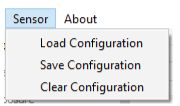
| Load Configuration | Replace the current sensor configuration with the stored configuration from the configuration file. |
| Save Configuration | Store the current sensor configuration to the configuration file. |
| Clear Configuration | Deletes the stored configuration entries of the currently connected sensor from the configuration file. |