Install the Autofocus Module and In-Sight Illumination
Complete the following steps to install the autofocus module accessory (ISAF-7000-8mm) and illumination accessory (ISLM-7000-WHI).
- The autofocus module has an 8mm M12 lens pre-installed. If a different lens is required, it should be installed into the autofocus module before the autofocus module is installed to the vision system. For more information, see Replace the M12 Autofocus Lens (Optional).
- For the In-Sight 7905, the S-Mount/M12 lens image circle size is smaller than the vision system’s image sensor size, resulting in mechanical vignetting in the image when using any S-Mount/M12 lens. Therefore, S-Mount/M12 lenses are not recommended. For more information, see Mechanical Vignetting.
- The illumination accessory (ISLM-7000-xxx) is sold separately. It is the only cover available for the autofocus module and is required for IP67 rating.
- The vision system supports connecting an integrated illumination accessory to the vision system's faceplate and connecting an external light to the vision system's LIGHT connector, but does not support using both lighting devices simultaneously.
- When installing the illumination accessory (ISLM-7000-WHI):
- Do not hot-plug the illumination accessory. Verify the vision system is not receiving power when connecting or disconnecting the illumination accessory. Failure to remove power during this procedure may result in damage to the vision system and/or the illumination accessory.
- The vision system should be grounded, either by mounting the vision system to a fixture that is electrically grounded or by attaching a wire from the vision system’s mounting fixture to frame ground or Earth ground. If a ground wire is used, it should be attached to one of the four mounting points on the back plate of the vision system and not to the mounting points on the front of the vision system.
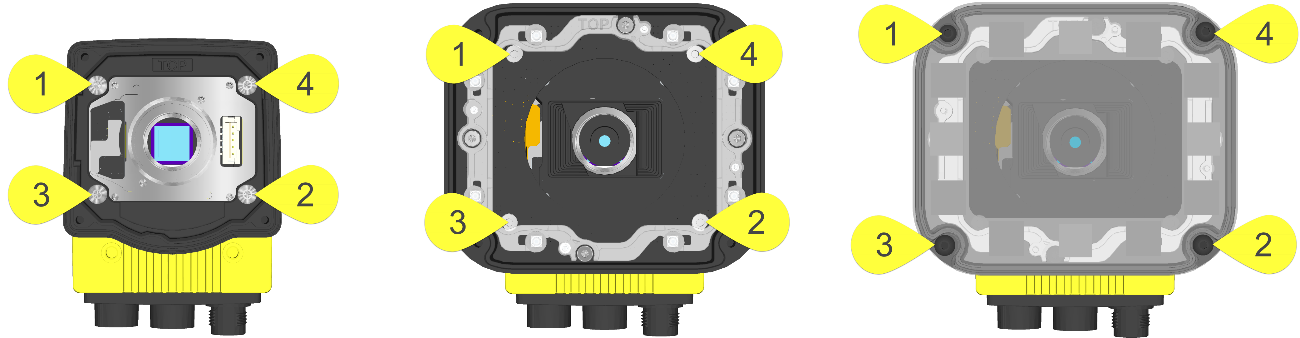
Tighten all illumination accessory screws in the following sequence.
- Remove the rubber faceplate covering the image sensor window, if present.
- Remove the protective film covering the threaded lens opening, if present.
-
Plug the PCB into the lighting connector on the vision system faceplate.
CAUTION: If uninstalling the PCB from the vision system, refer to Remove the Illumination Accessory PCB for steps to safely remove the PCB and avoid damage to the vision system.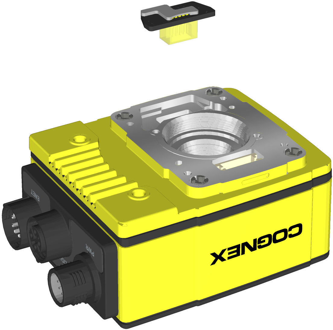
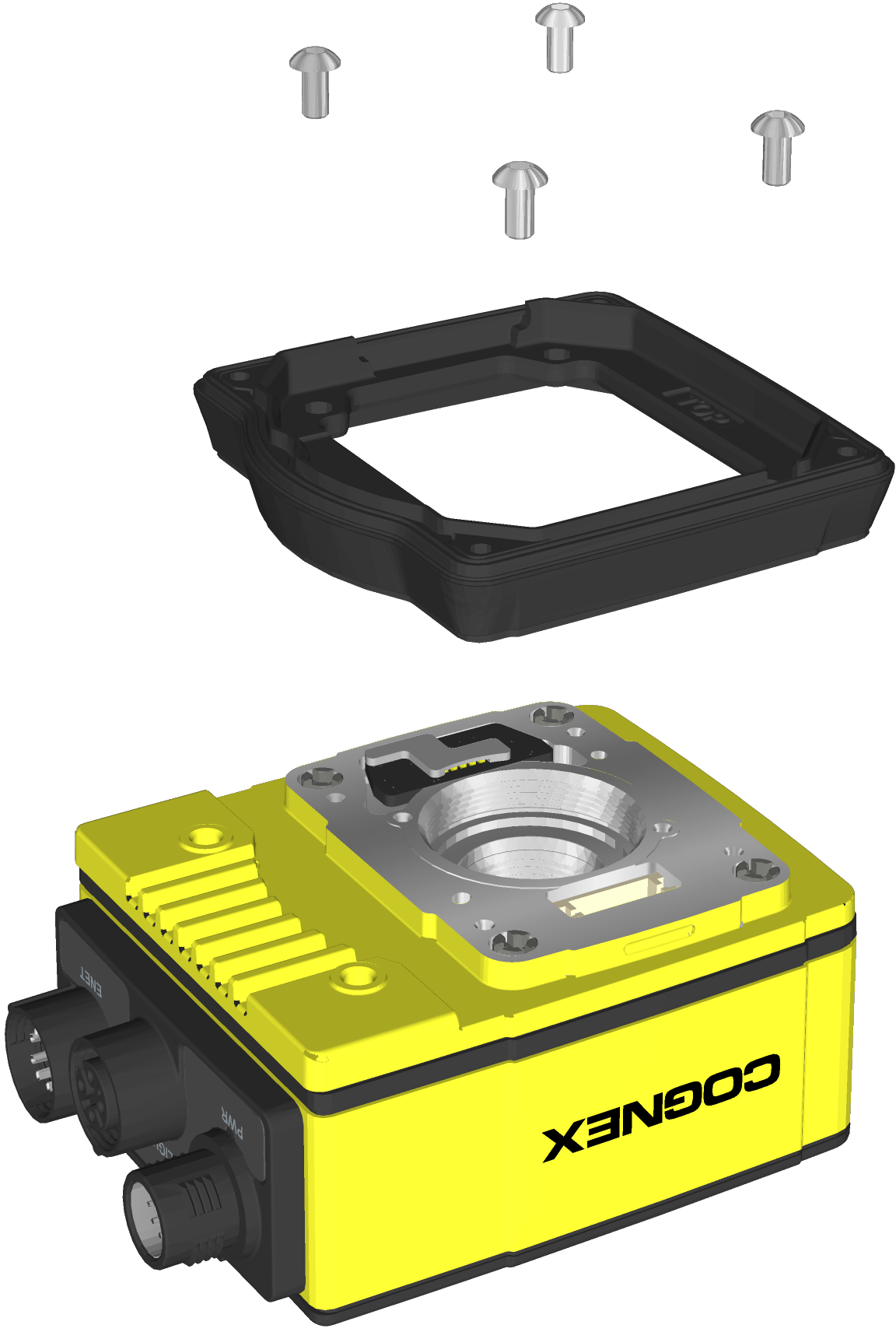
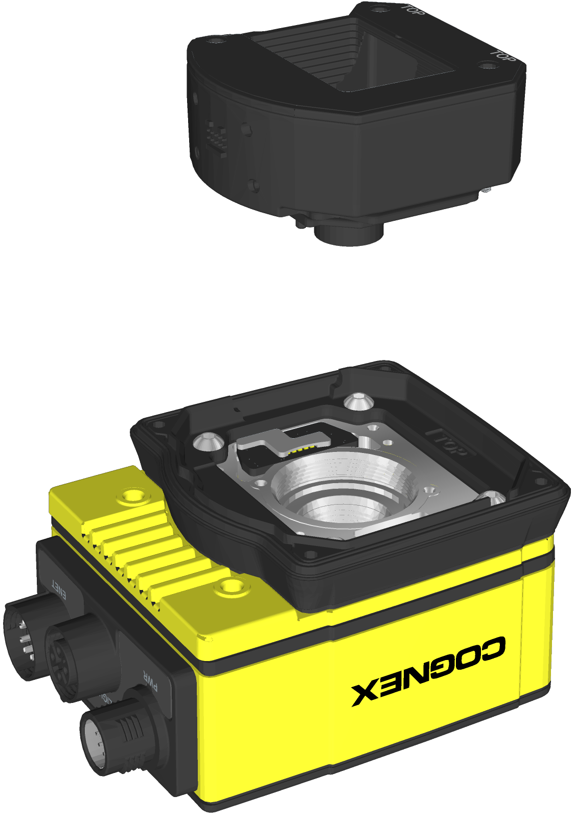
- Install the spacer.
- Place the spacer on top of the vision system with “TOP” oriented upward.
- Verify seating of the gasket on the bottom of the spacer.
Insert the four M3 screws and use a 2mm hex wrench to torque screws to 0.34 Nm (3 in-lb). For the 7500, 7501, 7600, 7800, 7801, 7802, 7900, 7901 and 7902, use the M3 x 6mm screws. For the 7802P, 7902P and 7905, use the M3 x 8mm screws.
- Install the autofocus module.CAUTION: Do not hot-plug the autofocus module. Verify the vision system is not receiving power when connecting or disconnecting the autofocus module.Note: If a different lens is required, it should be installed in the autofocus module before the autofocus module is installed to the vision system. For more information, see Replace the M12 Autofocus Lens (Optional).
- There are two alignment pins on the base of the autofocus module. Seat the pins into the vision system faceplate.
- There are three captive screws in the autofocus module. Partially thread the screws into the vision system faceplate using a 1.5mm hex wrench.
Once threaded, torque the captive screws to 0.5 Nm (4.43 in-lb) using a torque screwdriver with a 1.5mm hex torque bit capable of reaching 15mm into a 2.5mm diameter hole. For example, Wiha Tools 1.5mm Hex Metric Torque Blade (SKU 28545) used with the Adjustable Torque Handle (SKU 28550).
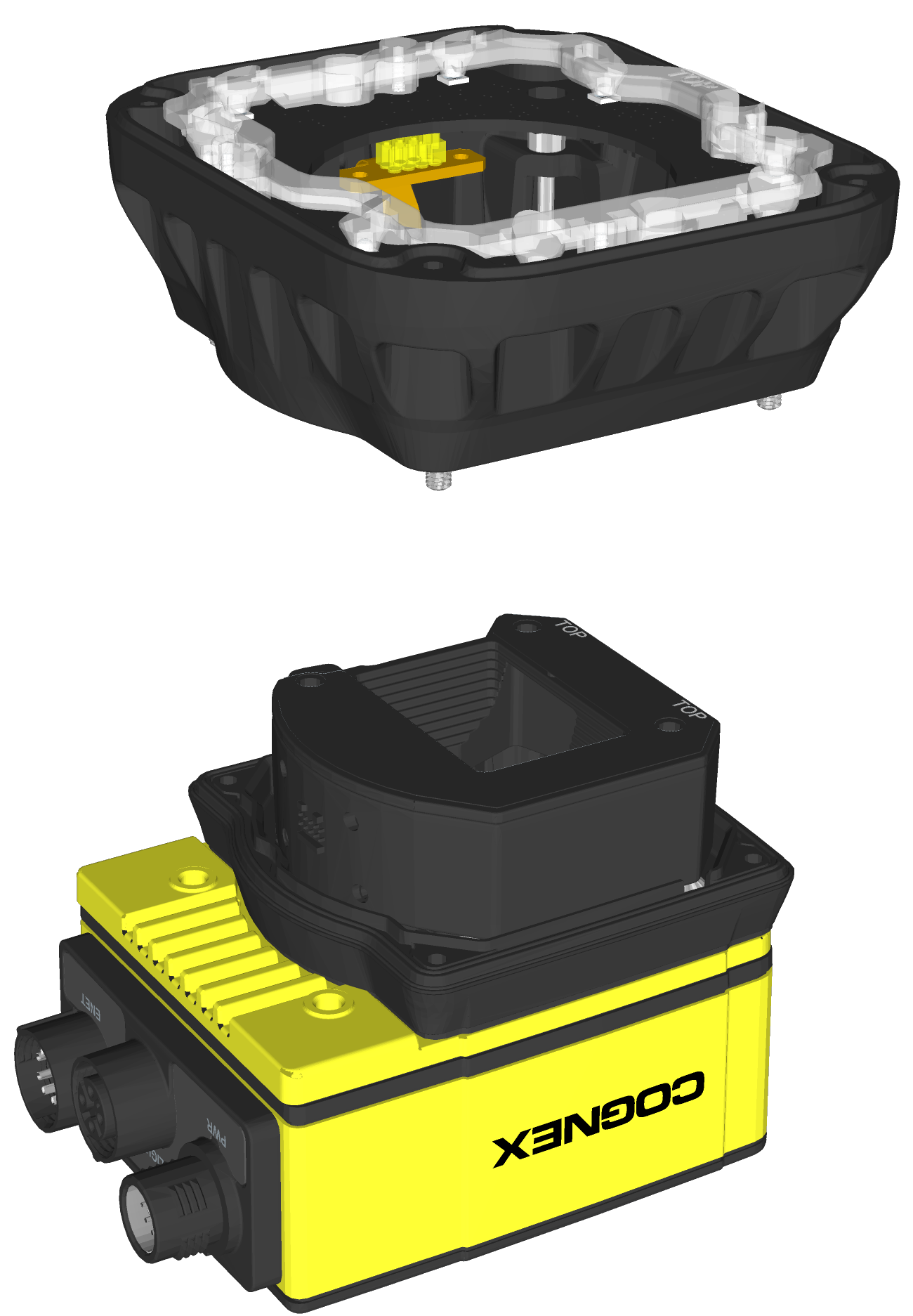
- Install the light housing.CAUTION:
- Do not hot-plug the LED ring light. Verify the vision system is not receiving power when connecting or disconnecting the LED ring light.
- A connector protrudes from the underside of the light housing. To prevent damage, it is recommended the light housing not be removed from the box until ready to be assembled.
Note: If a different LED color is required, refer to Replace the LED Ring Light (Optional).- Place the light housing with LED ring light on top of the spacer, with “TOP” oriented upward.
- Verify seating of the gasket on the top of the spacer.
There are four captive screw access holes near the white circles on the LED ring light. Use a 2mm hex wrench to torque the captive screws to 0.34 Nm (3 in-lb).
-
Optionally, install a bandpass filter to the light baffle.
Tip: Wear gloves when installing the filter to prevent leaving fingerprints on the surface of the filter.-
Insert the filter in the light baffle so it is held in place between the light baffle's filter retention tabs. Both sides of the filter are the same; either side of the filter can be oriented up or down when inserted in the light baffle.

-
Push the filter down and snap it into place, ensuring the filter retention tabs are flush with the top surface of the filter.

-
- Install the light baffle.
- Tilt the light baffle toward the light housing and maneuver the light baffle past the top of the LED ring light structure.
Compress the light baffle and maneuver the bottom of the light baffle past the bottom of the LED ring light structure until the light baffle snaps into place, with the keyed tabs sitting flush over each light housing captive screw access hole.
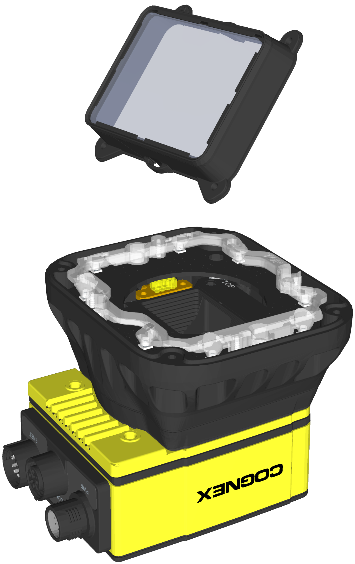
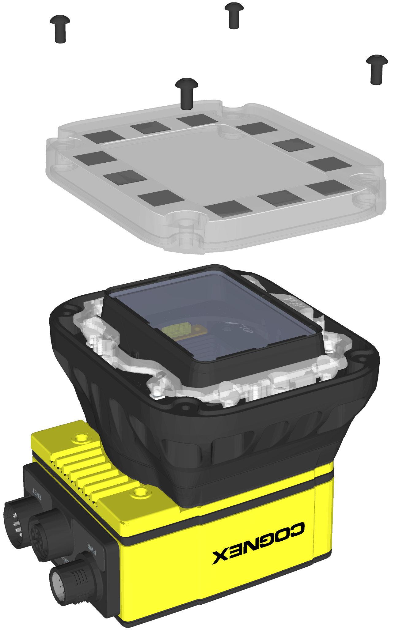
- Install the cover.
- Place the cover on the light housing.
- Align the central clear region of the cover with the light baffle edges.
Insert the four M3 x 12mm screws and use a 2mm hex wrench to torque screws to 0.31 Nm (2.75 in-lb).