Replace the M12 Autofocus Lens (Optional)
The autofocus module accessory (ISAF-7000-8mm) has an 8mm M12 lens pre-installed. Complete the following steps to replace the pre-installed M12 lens.
- Do not hot-plug the illumination accessory. Verify the vision system is not receiving power when connecting or disconnecting the illumination accessory. Failure to remove power during this procedure may result in damage to the vision system and/or the illumination accessory.
-
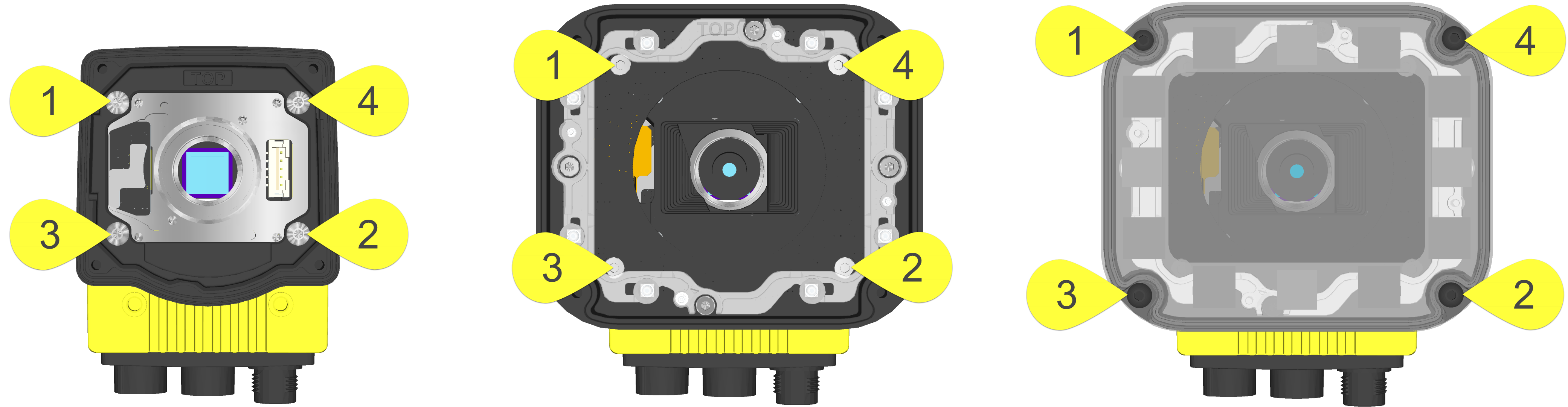
Tighten all illumination accessory screws in the following sequence.
- If the autofocus module is already installed to the vision system, you must first log onto the vision system using In‑Sight Explorer software and reset the focus position to 0. Refer to the In‑Sight ® Explorer Help file for more information.
- Remove power from the vision system.
-
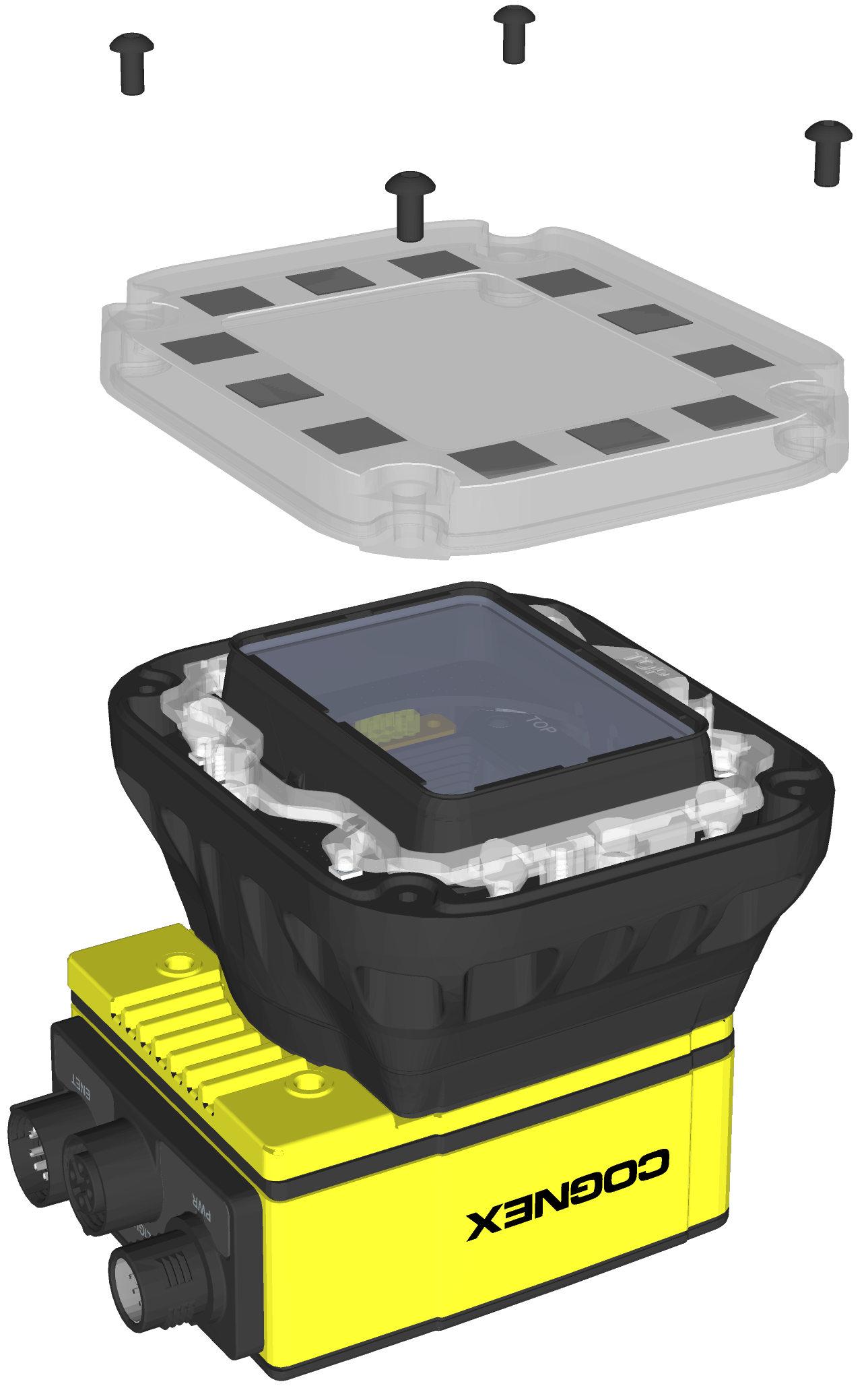
Use a 2mm hex wrench to remove the four M3 x 12mm screws and remove the cover.
-
Remove the keyed light baffle.
Note: This step includes an optional bandpass filter accessory installed to the light baffle. For more information, refer to In-Sight Lenses, Lights and Covers.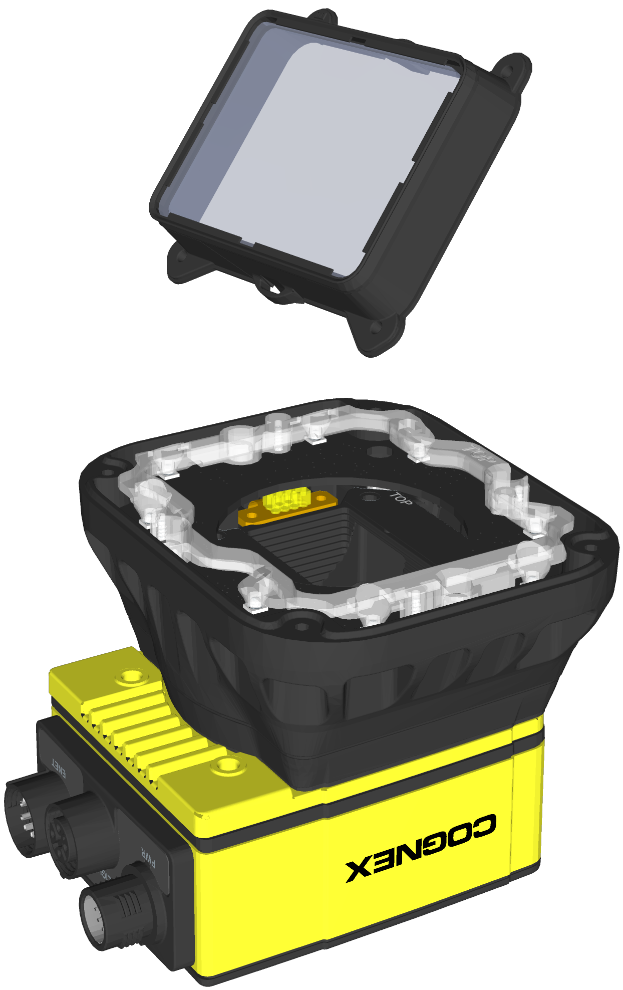
-
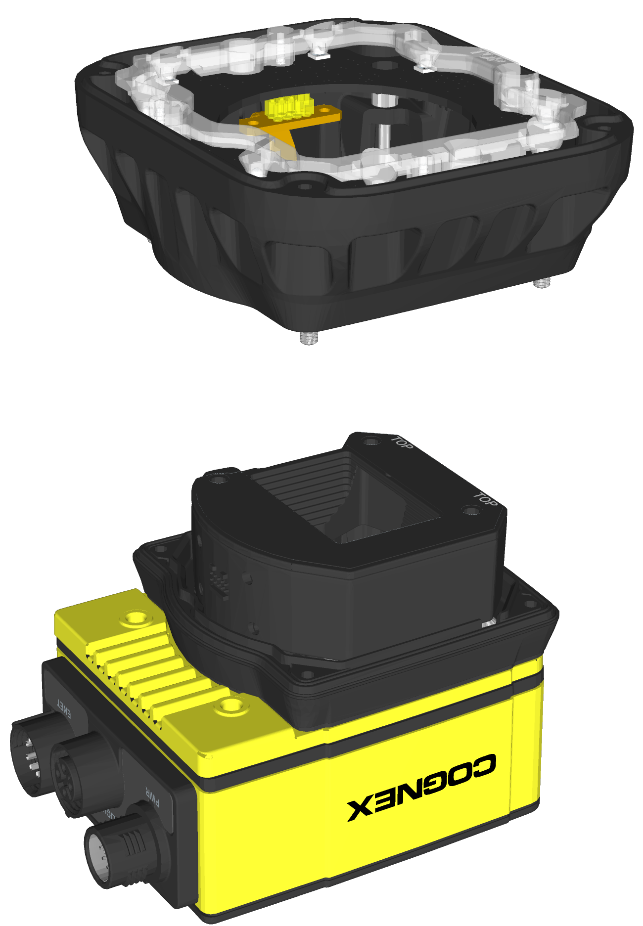
The light housing contains four captive screws that are accessible via captive screw access holes in the LED ring light board. Use a 2mm hex wrench to loosen the four captive screws and remove the light housing.
CAUTION:- Do not hot-plug the LED ring light. Verify the vision system is not receiving power when connecting or disconnecting the LED ring light.
- A connector protrudes from the underside of the light housing and can be damaged if placed on a hard surface.
-
Use a 1.5mm hex wrench to loosen the three captive screws in the autofocus module and remove the autofocus module from the vision system.
CAUTION: Do not hot-plug the autofocus module. Verify the vision system is not receiving power when connecting or disconnecting the autofocus module.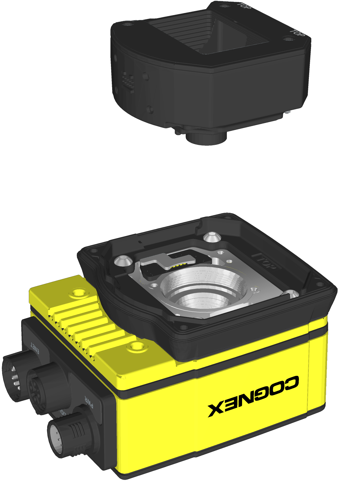
- Remove the M12 lens from the autofocus module.
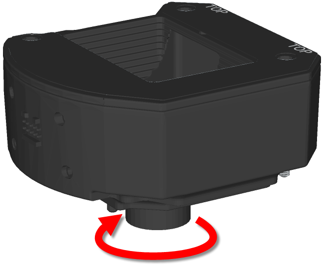
Remove the blue threaded lens nut on the underside of the autofocus module.
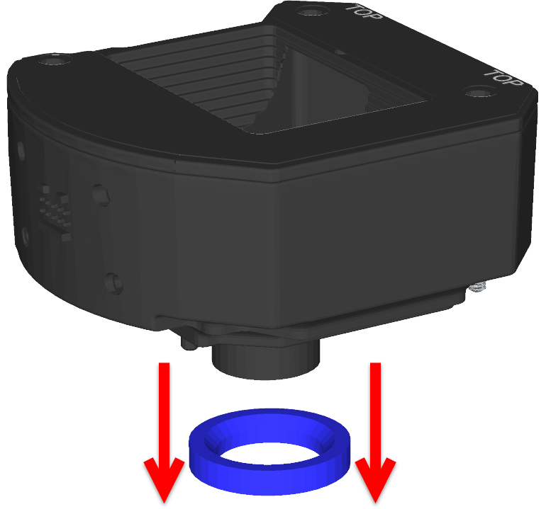
Remove the M12 lens from the autofocus module.

- Install the new M12 lens.
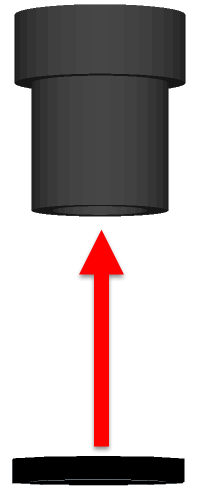
An extra black lens nut is included with the lens toolkit accessory (ISAF-7000-TOOL). Thread this black lens nut on the new M12 lens until snug.
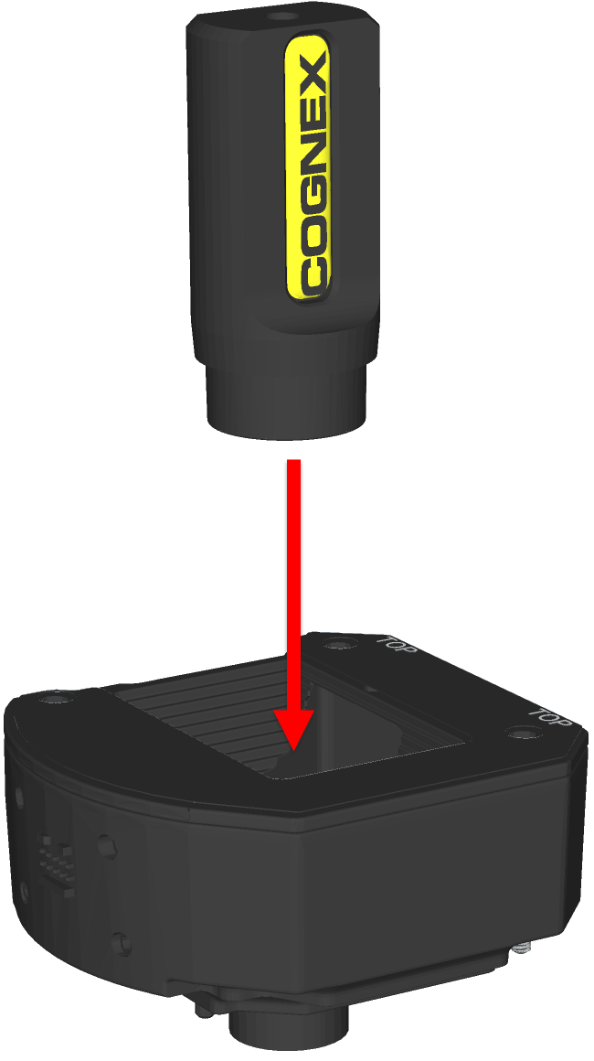
Drop the new M12 lens into the module.
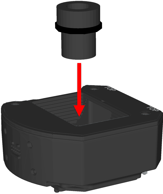
Quarter-turn the thread of the lens clockwise, to ensure the lens is seated in the lens carrier.
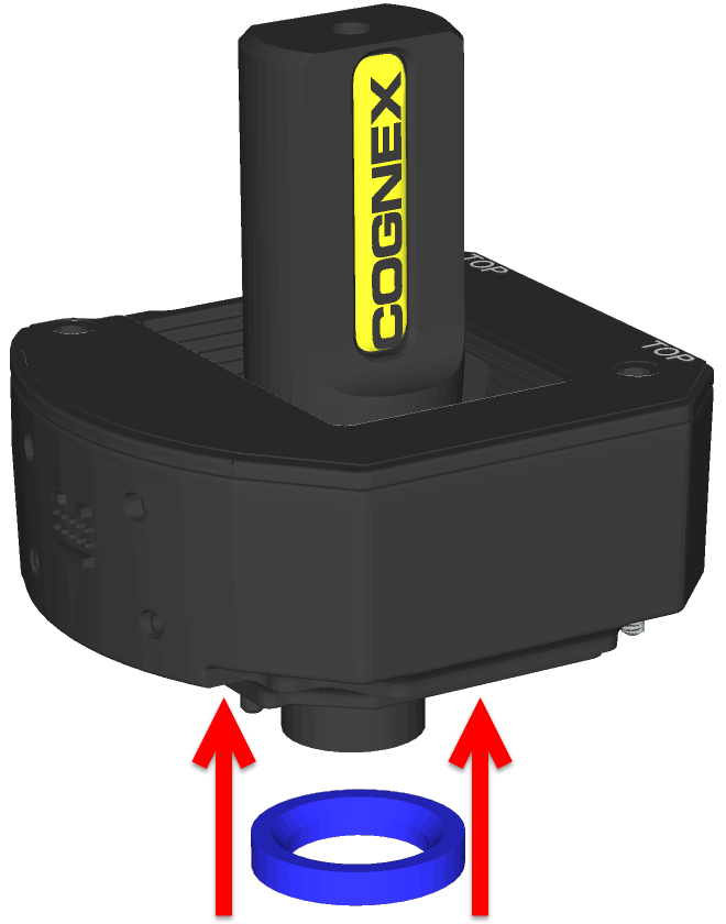
Once the lens is in the module, place the lens tool directly on the lens, with the padded end of the tool pressed against the lens.
With the lens tool, apply just enough pressure on the front of the lens to prevent the lens from moving. With the chamfer side of the blue lens nut facing the module, screw the blue nut onto the back of the lens. Once the threads of the blue nut are engaged with the lens, remove the lens tool and continue threading the blue nut until it is snug against the focus mechanism. The lens nut should be tight enough that it does not fall off due to vibration.
CAUTION: Use light axial force on the lens tool when installing or removing the lens.Chamfer Side of Blue Lens Nut: 
- Install the autofocus module.CAUTION: Do not hot-plug the autofocus module. Verify the vision system is not receiving power when connecting or disconnecting the autofocus module.
- There are two alignment pins on the base of the autofocus module. Seat the pins into the vision system faceplate.
- There are three captive screws in the autofocus module. Partially thread the screws into the vision system faceplate using a 1.5mm hex wrench.
Once threaded, torque the captive screws to 0.5 Nm (4.43 in-lb) using a torque screwdriver with a 1.5mm hex torque bit capable of reaching 15mm into a 2.5mm diameter hole. For example, Wiha Tools 1.5mm Hex Metric Torque Blade (SKU 28545) used with the Adjustable Torque Handle (SKU 28550).
- Install the light housing.CAUTION:
- Do not hot-plug the LED ring light. Verify the vision system is not receiving power when connecting or disconnecting the LED ring light.
- A connector protrudes from the underside of the light housing and can be damaged if placed on a hard surface.
Note: If a different LED color is required, refer to Replace the LED Ring Light (Optional).- Place the light housing with LED ring light on top of the spacer, with “TOP” oriented upward.
- Verify seating of the gasket on the top of the spacer.
There are four captive screw access holes near the white circles on the LED ring light. Use a 2mm hex wrench to torque the captive screws to 0.34 Nm (3 in-lb).
- Install the light baffle.Note: This step includes an optional bandpass filter accessory installed to the light baffle. For more information, refer to In-Sight Lenses, Lights and Covers.
- Tilt the light baffle toward the light housing and maneuver the light baffle past the top of the LED ring light structure.
Compress the light baffle and maneuver the bottom of the light baffle past the bottom of the LED ring light structure until the light baffle snaps into place, with the keyed tabs sitting flush over each light housing captive screw access hole.
- Install the cover.
- Place the cover on the light housing.
- Align the central clear region of the cover with the light baffle edges.
Insert the four M3 x 12mm screws and use a 2mm hex wrench to torque screws to 0.31 Nm (2.75 in-lb).
- Restore power to the vision system.