Connect the CIO-MICRO I/O Module (Optional)
The following steps illustrate how to connect the vision system to the In-Sight CIO‑MICRO I/O module.
- The CIO-MICRO I/O module supports In-Sight 8000 series vision systems with firmware version 5.3.0 and higher.
- The In-Sight 8500 series vision system must be connected to a Class 0, 3 or 4 PoE power source, rated for at least 12.95 Watts. The CIO-MICRO I/O module is a Class 2 PoE device and therefore cannot be used to supply power to the In-Sight 8500 series vision system via the I/O module's PoE port. Instead, connect the In‑Sight 8500 series vision system's Ethernet cable to a Class 0, 3 or 4 PoE power source and establish a connection to I/O module over the local area network using In-Sight Explorer. For more information, see Connect the Ethernet Cable.
- I/O wiring or adjustments to I/O devices should be performed when the vision system is not receiving power.
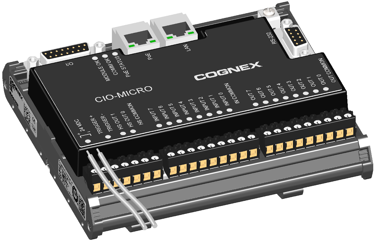
- Verify that the 24VDC power supply is unplugged and not receiving power.
- Use a screwdriver to loosen the I/O module's power terminals (labeled 24VDC + and –).
- Insert the 24VDC + and – wires (16 - 22 AWG, solid or stranded wire) from the power supply into the 24VDC + and – terminals on the I/O module.
-
Tighten the screw terminals with the screwdriver to secure the wire leads in the terminal block; the maximum torque is 0.1921 Nm (1.7 in-lb).
-
Connect a frame ground wire to the I/O module’s Frame Ground terminal. Connect the other end of the frame ground wire to frame ground.
CAUTION: The shield ground connections of the RS-232 port, LAN port, PoE port, I/O port and Frame Ground terminal are internally connected. The system grounding is at a zero ground potential. This zero-ground potential extends through the cable and to peripheral equipment, such as a vision system or PLC. To ensure safe operating conditions, check ground connections to ensure that they meet a zero ground potential.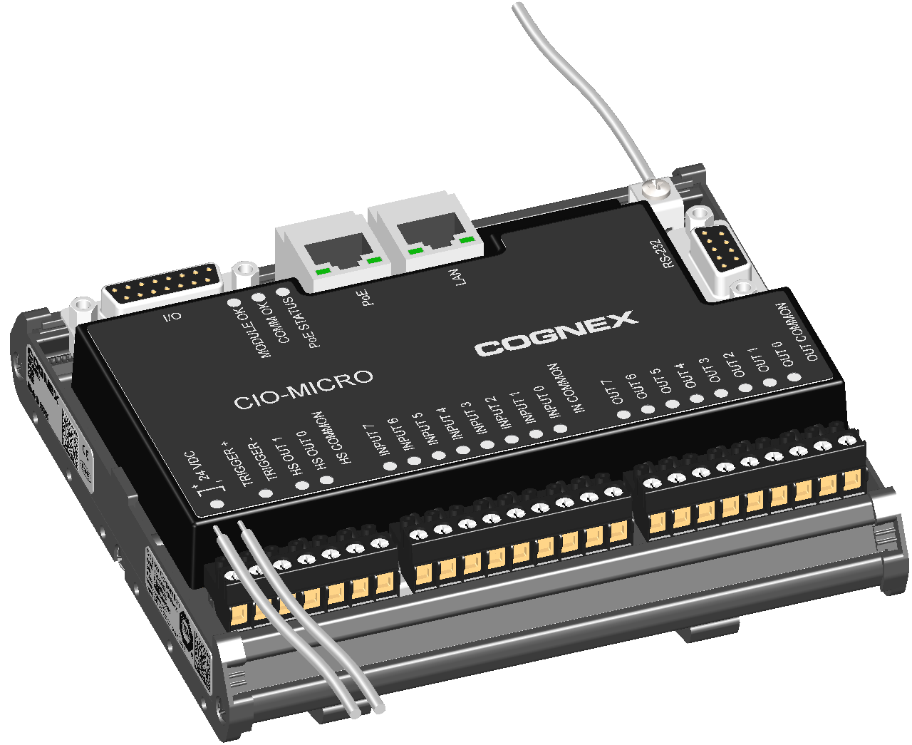
-
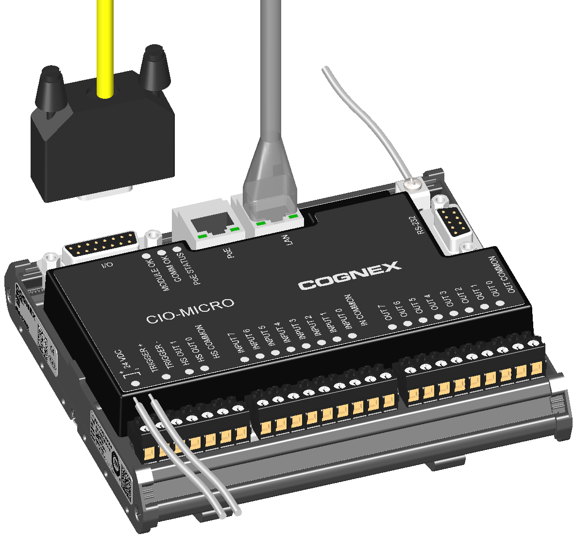
To connect the vision system to an Ethernet network, plug a LAN cable (RJ-45 connector) into the I/O module’s LAN port and connect the other end of the cable to a switch/router or PC, as applicable.
Note: The CIO-MICRO I/O module does not support 1000 BaseT pass-through operation. If 1000 BaseT operation is required, you must connect an RJ-45 LAN cable from a Gigabit PoE switch to the I/O module’s LAN port and connect the vision system’s Ethernet cable to the Gigabit PoE switch.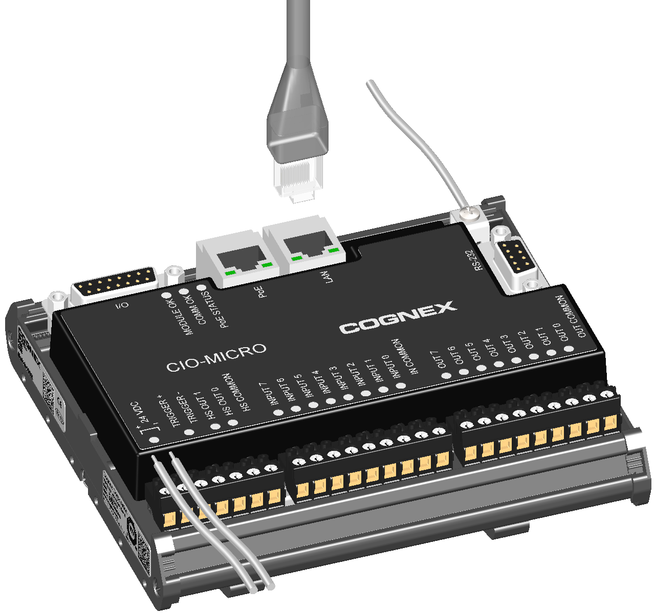
-
If installing the In-Sight 8405 vision system, attach the ferrite around the I/O Module cable, adjacent to the strain relief on the cable.
CAUTION: A ferrite is included with the In-Sight 8405vision system standard components. To reduce emissions, the ferrite must be attached to the I/O Module cable.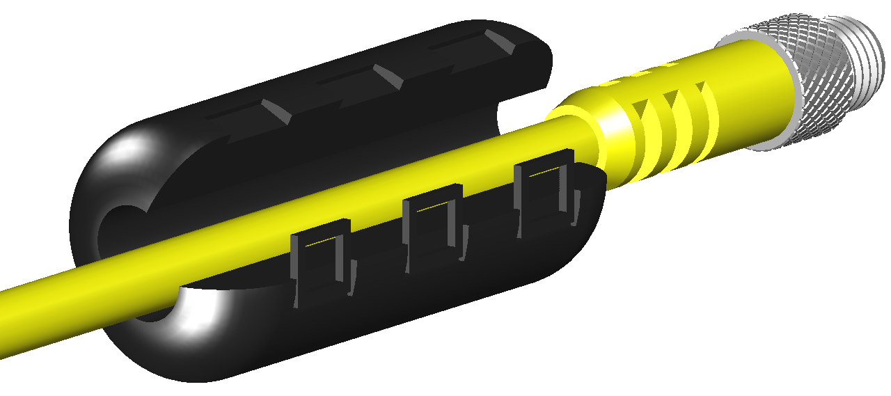
-
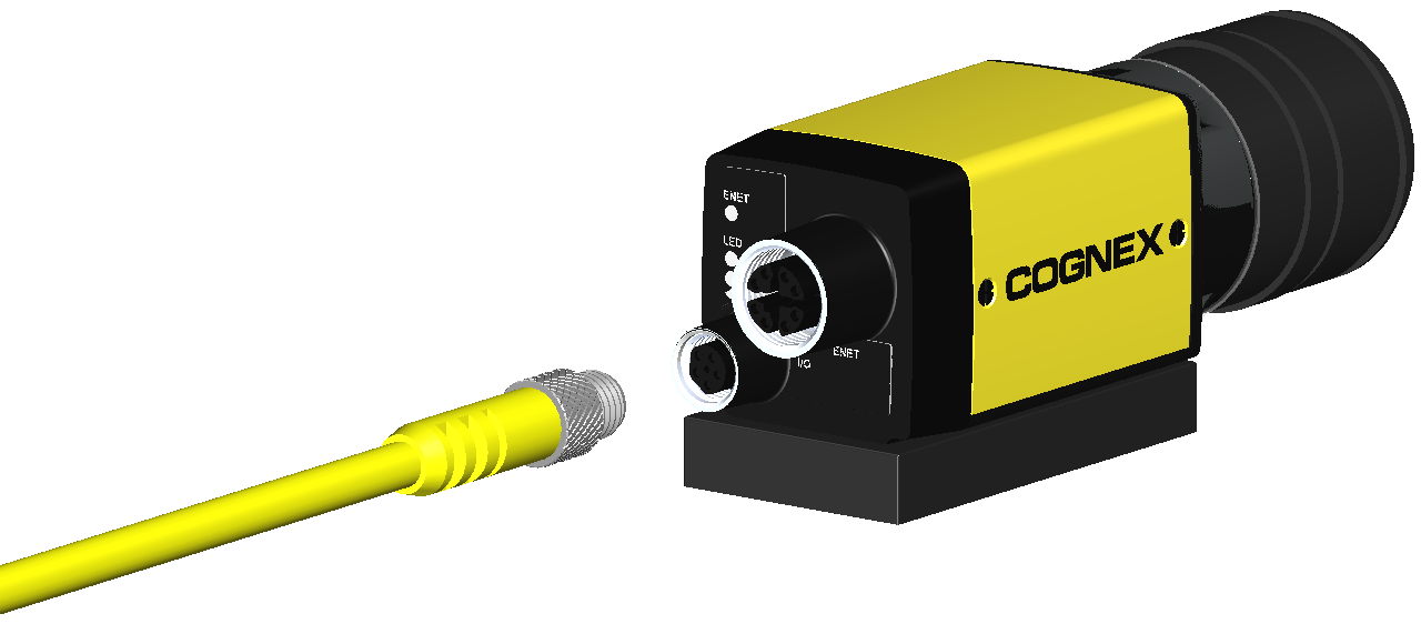
Connect the I/O Module cable's M8 connector to the vision system I/O connector.
-
Connect the I/O Module cable’s DB15 connector to the I/O module’s I/O connector.
-
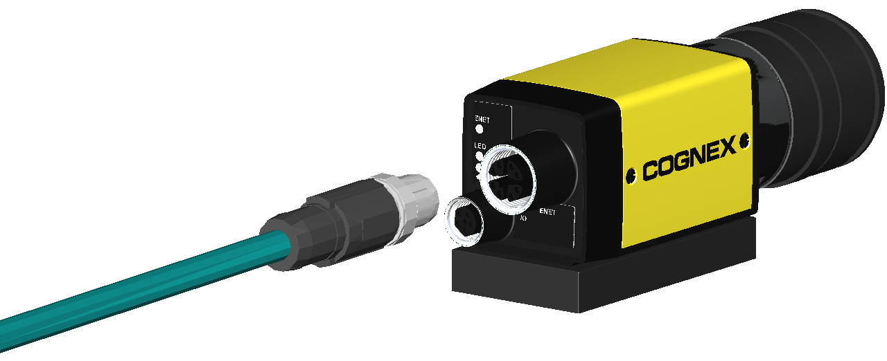
Connect the Ethernet cable's M12 connector to the vision system ENET connector.
CAUTION:- The Ethernet cable must be shielded. For the In-Sight 8405 vision system, Cognex strongly recommends Cat 6 or Cat 7 Ethernet cables with S/STP shielding.
- The Ethernet cable shield must be grounded at the far end.
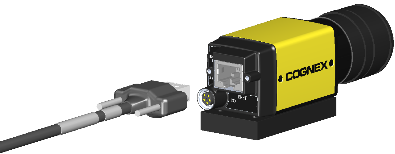
If installing the In-Sight 8405 vision system and using a compatible horizontal screw-locking Ethernet cable, use a screw driver to tighten the connector screws until snug. The screws must be tight to ensure a reliable connection.
-
Connect the Ethernet cable’s RJ-45 connector to the I/O module’s PoE port.
CAUTION: The I/O module’s PoE port provides power and Ethernet connectivity to the In-Sight 8100, 8200 or 8400 series vision system. If you connect third-party devices to the I/O module's PoE port, you could damage the I/O module.Note: The In-Sight 8500 series vision system must be connected to a Class 0, 3 or 4 PoE power source, rated for at least 12.95 Watts. The CIO-MICRO I/O module is a Class 2 PoE device and therefore cannot be used to supply power to the In-Sight 8500 series vision system via the I/O module's PoE port. Instead, connect the In‑Sight 8500 series vision system's Ethernet cable to a Class 0, 3 or 4 PoE power source and establish a connection to I/O module over the local area network using In-Sight Explorer. For more information, see Connect the Ethernet Cable.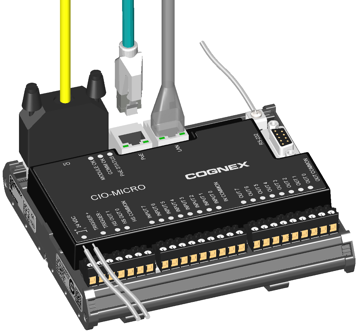
- Restore power to the I/O module’s 24VDC power supply and turn it on if necessary.