TrainPatMaxRedLineColor
Extracts and trains a pattern (a trained, internal geometric description of an object you wish to find) from a color image for use with the FindPatMaxRedLineColor function. For more information, see FindPatMaxRedLineColor.
- The TrainPatMaxRedLineColor and FindPatMaxRedLineColor functions are only available on In-Sight 7000 Gen2 series color vision systems and In-Sight 8000 series color vision systems running In-Sight firmware 5.6.0 and later. For a complete list of models and supported firmware versions, see Firmware Versions.
- When using a greyscale image, the TrainPatMaxRedLine and FindPatMaxRedLine function must be used. When attempting to use the TrainPatMaxRedLineColor and FindPatMaxRedLineColor functions on a greyscale image (for example, ColorToGreyscaleFilter's output), #ERR is returned.
- The FindPatMaxRedLineColor function must reference the TrainPatMaxRedLineColor function. When referenced a different function (for example, a TrainPatMaxRedLine function), #ERR is returned.
TrainPatMaxRedLineColor Inputs
Sytanx: TrainPatMaxRedLineColor(Image,Fixture.Row,Fixture.Column,Fixture.Theta,Pattern Region.X,Pattern Region.Y,Pattern Region.High,Pattern Region.Wide,Pattern Region.Angle,Pattern Region.Curve,External Region,Pattern Origin.Offset Row,Pattern Origin.Offset Column,Match Colors,Select Colors,Auto Select Coarse,Auto Select Fine,Coarse Granularity,Fine Granularity,Feature Threshold,Reuse Training Image,Timeout,Show Graphics)
| Parameter | Description | ||||||||||||
|---|---|---|---|---|---|---|---|---|---|---|---|---|---|
|
Specifies a reference to a spreadsheet cell that contains an Image data structure; by default, this parameter references A0, the cell containing the AcquireImage Image data structure. This parameter can also reference other Image data structures, such as those returned by the Vision Tool Image functions or Coordinate Transforms Functions. Note: This parameter must reference a color image.
|
|||||||||||||
|
Defines the Region of Interest (ROI) relative to a Fixture input or the output of a Vision Tool function's image coordinate system. Setting the ROI relative to a Fixture ensures that if the Fixture is rotated or translated, the ROI will be rotated or translated in relation to the Fixture. For more information, see Fixture and Vision Tools. Note: The default setting is (0,0,0), the top leftmost
corner of the image.
|
|||||||||||||
|
Also known as the Region of Interest (ROI), specifies the region of the image that undergoes analysis and creates a rectangular image region that can be transformed and rotated. For more information, see Interactive Graphics Mode.With this parameter selected, you can press the Maximize Region button on the property sheet's toolbar to maximize the region and cover the entire image.
|
|||||||||||||
|
This parameter can reference a spreadsheet cell that contains the following functions:
When this parameter is used, the function ignores the Region and Fixture settings and inspects the image area specified by referenced region. If an EditCompositeRegion control is referenced, the inspection area can be a mix of shapes. Each shape in the composite region can be assigned as added to or subtracted from (masking) the inspection area. For more information, see Cell References - Relative/Absolute. Note: If this parameter has been set as a reference to an external region, to use the function's internal Region, this parameter must be manually set to zero by entering the value 0 in place of the cell reference. Otherwise, the function will continue to reference the external region.
|
|||||||||||||
|
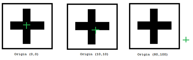
Specifies the row and column of the training pattern's origin, as offsets from the center of the training region.
|
|||||||||||||
| Match Colors |
Specify which colors to train in the Pattern Region.
|
||||||||||||
|
|
Specifies colors to train by using the Select Colors dialog. You may reference a button or a numeric value in the job; non-zero values are treated as a pressed button and will trigger the Select Colors dialog. For more information, see Selecting Colors.
Note: The Select Colors parameter is enabled only when the Match Colors parameter is set to Selected Colors.
|
||||||||||||
|
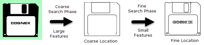
Specifies whether or not automatically specify the image granularity to use for the coarse search phase. Coarse granularity is used to find large features to find an approximate pattern match in a run-time image quickly.
|
|||||||||||||
| Auto Select Fine |
Specifies whether or not automatically specifies the image granularity to use for the fine search phase. Fine granularity is used to find small features to determine the pattern location precisely.
|
||||||||||||
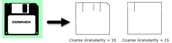
| Coarse Granularity |
Specifies the coarse granularity, as a pixel value. Coarse granularity is used to find large features to find an approximate pattern match in a run-time image quickly (1 to 30; 4 = default). Note: The Auto Select Coarse parameter is enabled by default; disable it to enable this parameter.
|
||||||||||||
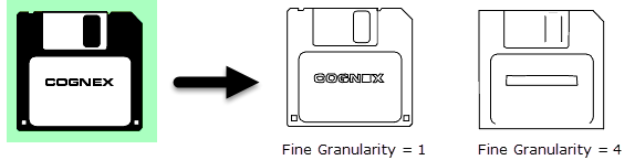
| Fine Granularity |
Specifies the fine granularity, as a pixel value. Fine granularity is used to find small features to determine the pattern location precisely (1 to 10; 1 = default). Note:
|
||||||||||||
| Feature Threshold |
Specifies the minimum contrast of trained features; decrease the value to train additional low contrast features, or increase it to ignore them (1 to 100; 20 = default). |
||||||||||||
| Reuse Training Image |
Specifies whether or not the image used to train the pattern is saved and used when modifying the Pattern settings parameters (Pattern Origin, Auto Select Coarse, Auto Select Fine, Coarse Granularity, Fine Granularity).
|
||||||||||||
|
Specifies the amount of time, in milliseconds (0 to 30000; default = 0, disabling the timeout), that the function will search for a valid pattern before execution is halted and an #ERR is returned. |
|||||||||||||
|
Specifies the display mode for TrainPatMaxRedLineColor graphics on the image.
|


TrainPatMaxRedLineColor Outputs
|
Returns |
A Patterns data structure containing a trained pattern, or #ERR if any of the input parameters are invalid. The function is Disabled by default to avoid accidentally training a new pattern on the next acquisition. For more information, see Cell State Dialog. |
|
When TrainPatMaxRedLineColor is initially inserted into a cell, the Trained status automatically appears in the adjacent cell to the right. If a pattern cannot be trained, then #ERR is inserted. |
TrainPatMaxRedLineColor Vision Data Access Functions
One Vision Data Access function is automatically inserted into the spreadsheet. For more information, see Patterns.
| Name | VDA function | Description |
|---|---|---|
|
GetTrained(Pattern) |
Returns 1 if a pattern has been successfully trained, and 0 if a pattern cannot be trained. |
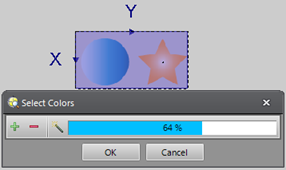
Selecting Colors
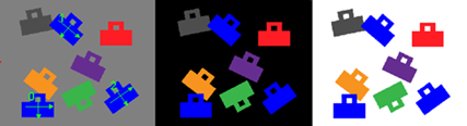
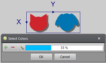
When the Match Colors parameter is set to Selected Colors, you need to select colors to train in the Pattern Region using the Select Colors dialog.
-
Click the Select Colors button in the TrainPatMaxRedLineColor property sheet. The Select Colors dialog and the magic wand cursor display.
-
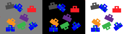
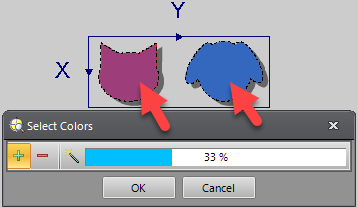
Click the areas where you want to train colors in the Pattern Region. Once selected, the selected areas are colored in and surrounded by a moving border.
 Note:
Note:- When selecting multiple areas, enable the
 icon in the Select Colors dialog or hold down the CTRL key, and click the areas.
 - When deselecting areas, enable the
 icon in the Select Colors dialog and click the areas.
 - If you click the outside of the Pattern Region, the selected areas are all deselected.
- When selecting multiple areas, enable the
-
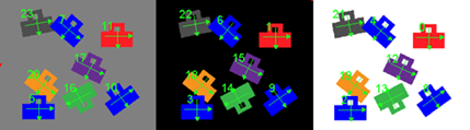
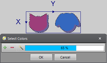
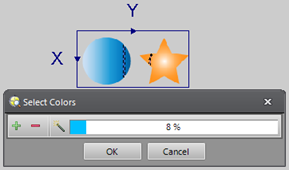
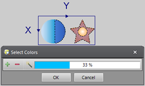
Specify the tolerance using the Select Colors dialog. To adjust the value, you can click within the bar, or drag the bar. The tolerance is applied once you release the mouse button.
 Note:
Note:The tool examines all the pixels that were clicked (= input pixel), and performs a basic diff operation. If the diff result is less than or equal to the tolerance value, the pixels are selected. If you increase the tolerance towards to 100%, all pixels within the Pattern Region are selected. If you decrease the tolerance to 0%, the only pixels that are the exact RBG value of the input pixel are selected.
-
To accept the selected colors and the tolerance, press the OK button. To cancel, click the Cancel button.
Tip: You can also click the or
or  button in the Job Edit Toolbar to accept or cancel.
 - The TrainPatMaxRedLineColor property sheet displays again.