Breakout Cable Specifications
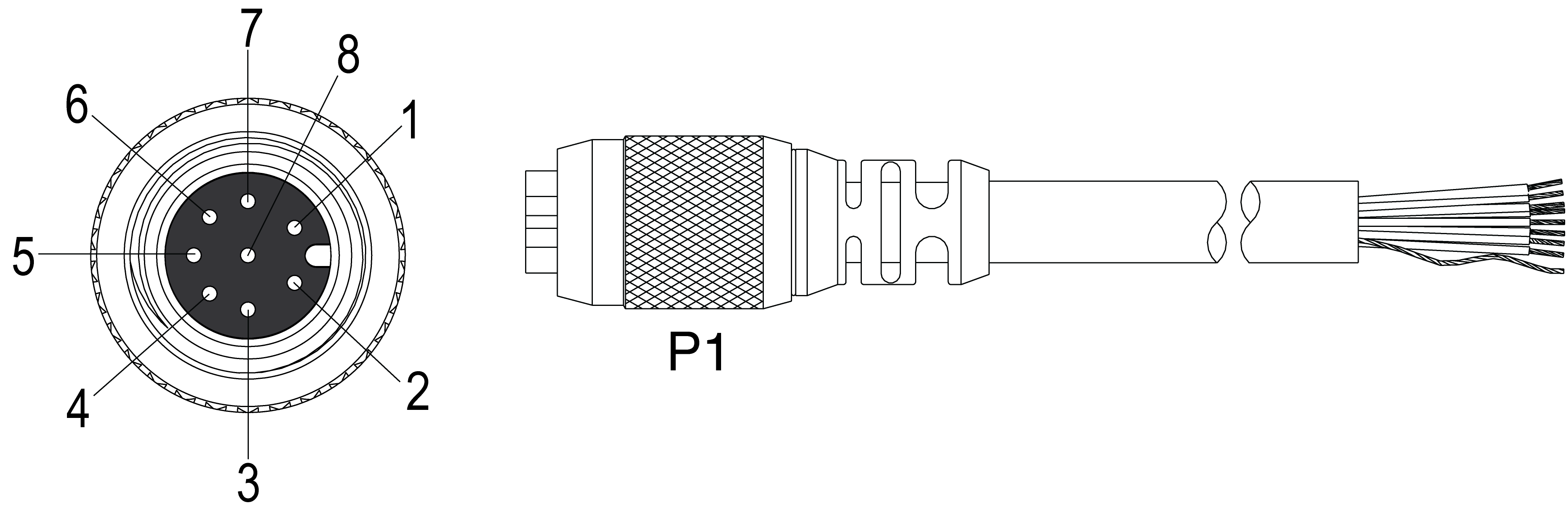
The Breakout cable provides connection to an external power supply, RS-232 serial communications, acquisition trigger input, high-speed outputs and encoder inputs (In-Sight 5604 only). The Breakout cable is not terminated. When using the In-Sight 5604, refer to Encoder Inputs (In-Sight 5604 Only).
|
||
|---|---|---|
| Pin# | Signal Name | Wire Color |
| 1 | +24VDC | White/Green |
| 2 | TRIGGER+ | Green |
| 3 | TRIGGER- | White/Orange |
| 4 | HSOUT 0 | Blue |
| 5 | HSOUT 1 | White/Blue |
| 6 |
RS-232 RECEIVE (RxD)1 (In-Sight 5604 Only: Encoder A) |
Orange |
| 7 |
RS-232 TRANSMIT (TxD)2 (In-Sight 5604 Only: Encoder B) |
White/Brown |
| 8 | 24V COMMON | Brown |
Note:
- Cables are sold separately.
- You can clip unused wires short or use a tie made of non-conductive material to tie them back. Keep bare wires separated from the +24VDC wire.
- The housing of the vision system is internally connected to the system ground wire (pin 8 of the Breakout cable). Therefore, if the mounting surface of the vision system is at a non-zero ground potential, it is strongly recommended that the vision system be mounted on an isolated or non-conductive mount.