TrainPatMaxRedLine
Extracts and trains a pattern from an image for use with the FindPatMaxRedLine function. For more information, see FindPatMaxRedLine.
- From In-Sight firmware 5.5.0 and later, the function's algorithm has been changed to return more accurate results and decrease the execution time in some circumstances.
- Due to this change, when attempting to load a job containing this function configured on the In-Sight firmware 5.5.0 or later to an In-Sight vision system running firmware version 5.4.x or earlier, an error message is displayed and any cells that contains this function will result in #ERR.
- This function is only available on In-Sight vision systems running In-Sight firmware 5.1.0 and later. For a complete list of models and supported firmware versions, see Firmware Versions.
- A trained pattern consumes approximately 1MB when using the default Pattern Region (320 x 440), although the pattern size varies greatly depending on the size of the trained pattern.
TrainPatMaxRedLine Inputs
Syntax: TrainPatMaxRedLine (Image,Fixture.Row,Fixture.Column,Fixture.Theta,Pattern Region.X,Pattern Region.Y,Pattern Region.High,Pattern Region.Wide,Pattern Region.Angle,Pattern Region.Curve,External Region,Pattern Origin.Offset Row,Pattern Origin.Offset Column,Auto Select Coarse,Auto Select Fine,Coarse Granularity,Fine Granularity,Feature Threshold,Reuse Training Image,Timeout,Show)
| Parameter | Description | ||||||||||||
|---|---|---|---|---|---|---|---|---|---|---|---|---|---|
|
Specifies a reference to a spreadsheet cell that contains an Image data structure; by default, this parameter references A0, the cell containing the AcquireImage Image data structure. This parameter can also reference other Image data structures, such as those returned by the Vision Tool Image functions or Coordinate Transforms Functions. |
|||||||||||||
|
Defines the Region of Interest (ROI) relative to a Fixture input or the output of a Vision Tool function's image coordinate system. Setting the ROI relative to a Fixture ensures that if the Fixture is rotated or translated, the ROI will be rotated or translated in relation to the Fixture. For more information, see Fixture and Vision Tools. Note: The default setting is (0,0,0), the top leftmost
corner of the image.
|
|||||||||||||
|
Also known as the Region of Interest (ROI), specifies the region of the image that undergoes analysis and creates a rectangular image region that can be transformed and rotated. For more information, see Interactive Graphics Mode. Tip: With this parameter
selected, you can press the Maximize
Region button on the property sheet's toolbar to maximize the region and cover the entire image.
|
|||||||||||||
|
This parameter can reference a spreadsheet cell that contains the following functions:
When this parameter is used, the function ignores the Region and Fixture settings and inspects the image area specified by referenced region. If an EditCompositeRegion control is referenced, the inspection area can be a mix of shapes. Each shape in the composite region can be assigned as added to or subtracted from (masking) the inspection area. For more information, see Cell References - Relative/Absolute. Note: If this parameter has been set as a reference to an external region, to use the function's internal Region, this parameter must be manually set to zero by entering the value 0 in place of the cell reference. Otherwise, the function will continue to reference the external region.
|
|||||||||||||
|
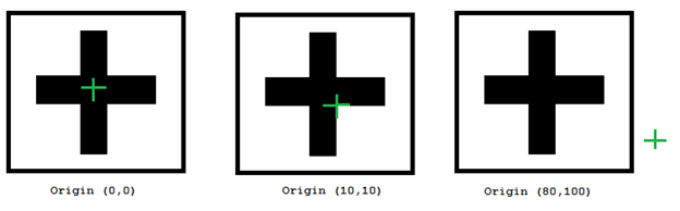
Specifies the row and column of the training pattern's origin, as offsets from the center of the training region.
|
|||||||||||||
|
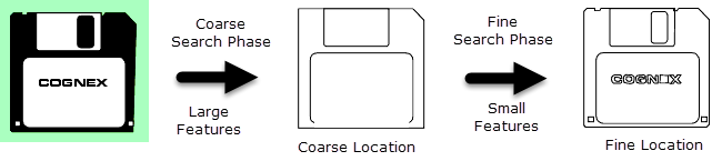
Specifies whether or not automatically specify the image granularity to use for the coarse search phase. Coarse granularity is used to find large features to find an approximate pattern match in a run-time image quickly.
|
|||||||||||||
| Auto Select Fine |
Specifies whether or not automatically specifies the image granularity to use for the fine search phase. Fine granularity is used to find small features to determine the pattern location precisely.
|
||||||||||||
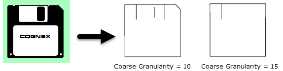
| Coarse Granularity |
Specifies the coarse granularity, as a pixel value. Coarse granularity is used to find large features to find an approximate pattern match in a run-time image quickly (1 to 30; 4 = default). Note: The Auto Select Coarse parameter is enabled by default; disable it to enable this parameter.
|
||||||||||||
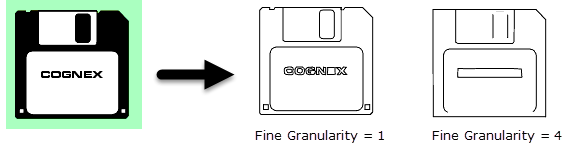
| Fine Granularity |
Specifies the fine granularity, as a pixel value. Fine granularity is used to find small features to determine the pattern location precisely (1 to 10; 1 = default). Note:
|
||||||||||||
| Feature Threshold |
Specifies the minimum contrast of trained features; decrease the value to train additional low contrast features, or increase it to ignore them (1 to 100; 20 = default). |
||||||||||||
| Reuse Training Image |
Specifies whether or not the image used to train the pattern is saved and used when modifying the Pattern settings parameters (Pattern Origin, Auto Select Coarse, Auto Select Fine, Coarse Granularity, Fine Granularity or Noise Threshold).
|
||||||||||||
|
Specifies the amount of time, in milliseconds (0 to 30000; default = 0, disabling the timeout), that the function will search for a valid pattern before execution is halted and an #ERR is returned. |
|||||||||||||
|
Specifies the display mode for TrainPatMaxRedLine graphics on the image.
|
TrainPatMaxRedLine Outputs
|
Returns |
A Patterns data structure containing a trained pattern, or #ERR if any of the input parameters are invalid. The function is Disabled by default to avoid accidentally training a new pattern on the next acquisition. For more information, see Cell State Dialog. |
|
When TrainPatMaxRedLine is initially inserted into a cell, the Trained parameter status automatically appears in the adjacent cell to the right. If a pattern cannot be trained, then #ERR is inserted. |
TrainPatMaxRedLine Vision Data Access Functions
One Vision Data Access function is automatically inserted into the spreadsheet. For more information, see Patterns.
| Name | VDA Function | Description |
|---|---|---|
| GetTrained(Pattern) |
Returns 1 if a pattern has been successfully trained, and 0 if a pattern cannot be trained. |