3D Toolbar
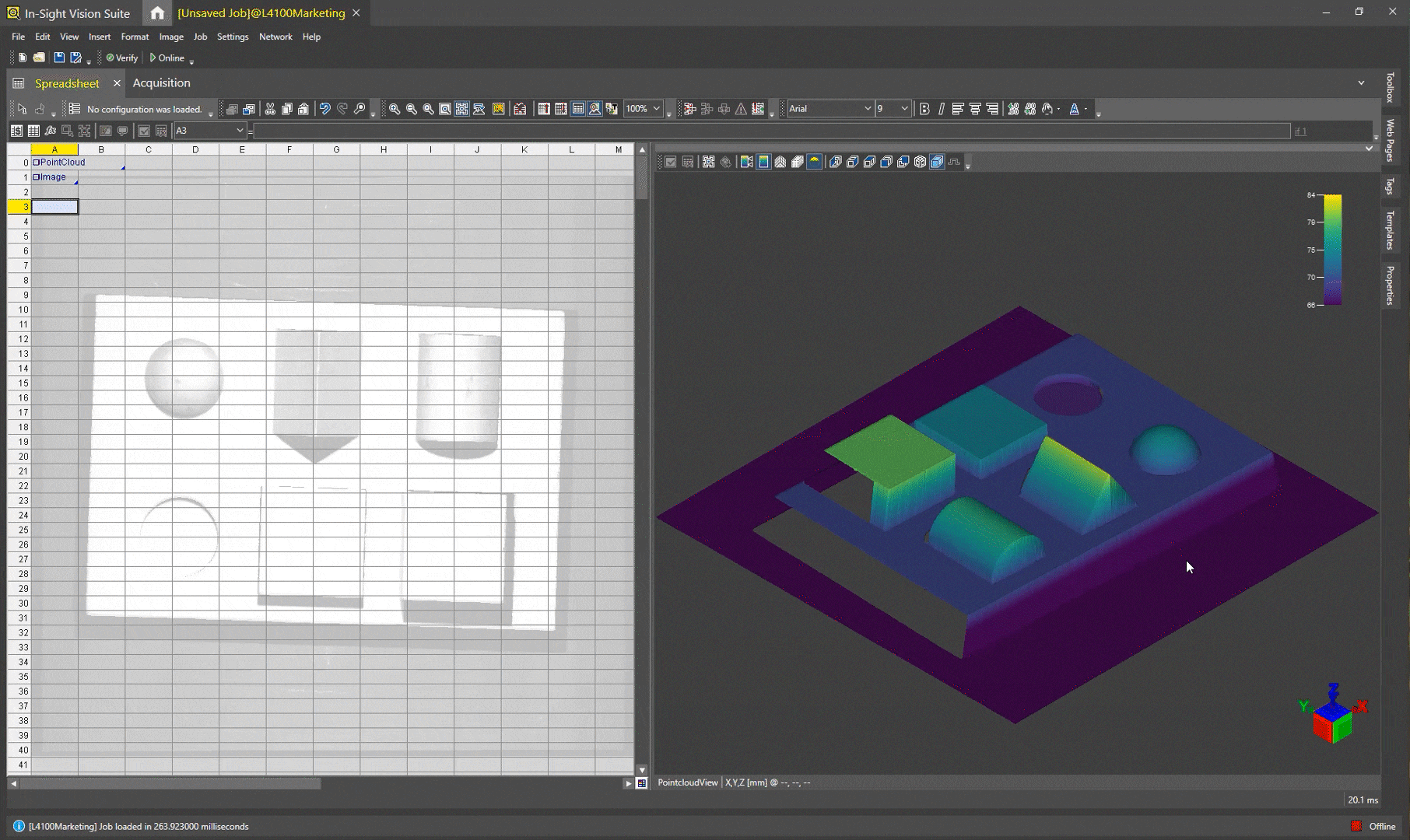
The 3D toolbar of the spreadsheet allows single-click access to various settings that you can use to manipulate the appearance of the acquired 3D point cloud.
| Icon | Tool | Description | ||||
|---|---|---|---|---|---|---|
|
|
Accept Changes |
Accept the current spreadsheet modification. This button is enabled only if a graphic editing is in progress. |
||||
|
|
Cancel Changes |
Cancel the current modification and restore previous values (if any). This button is enabled only if graphic editing is in progress. |
||||

|
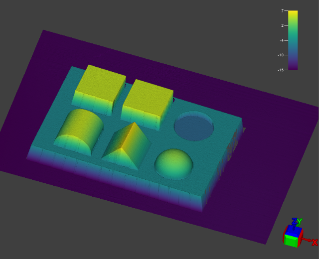
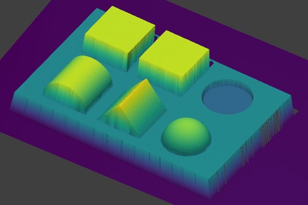
Color 3D Image By Height |
Enables the Z-Axis Height Color Map and the Color Map Legend, indicating the height of the point cloud points along the Z-axis, relative to the height coloring setup in the Spreadsheet Editor.
When color mapping is enabled, the warmer the point is, the closer it is to the top threshold (i.e., it is "higher" in the working space of the sensor). Consequently, the colder it is, the closer it is to the bottom threshold (i.e. the lower it is in the working area of the sensor). |
||||

|
Fit 3D Image to Window |
Fits the 3D point cloud to the display. The point cloud will automatically scale to be maximally displayed in the viewer. The original aspect ratio of the point cloud is also maintained, therefore it may not fill the viewer completely. |
||||

|
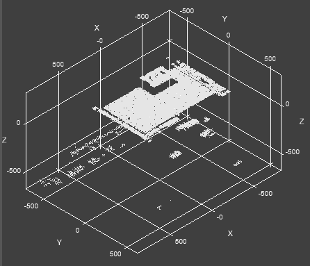
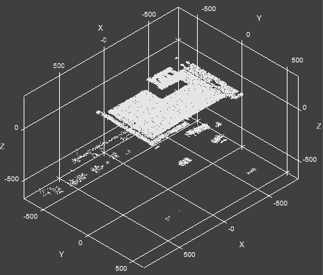
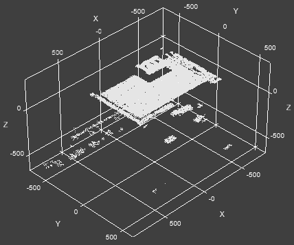
Toggle 3D Grid |
Toggles a 3D grid around the point cloud, indicating the planes, axes and distances within the point cloud space.
|
||||

|
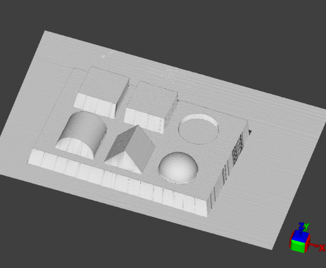
Toggle 3D Image Visualization as Points/Surface |
Allows you to switch between Mesh Mode (
|
||||
|
|
Ortographic/Perspective Toggle |
Allows you to switch between the orthographic and perspective views of the acquired image data.
Click the |
||||

|
Toggle Lambert Lighting |
Enables or disables ambient directional Lambert lighting in the 3D scene. When disabled, lighting is cast from the Z-axis. When enabled, it comes from the 3D viewer camera perspective. Tip: Enable or disable this setting based on which features of the acquired point cloud you wish to be visible.
|
||||

|
Show 3D Image From Left |
Changes the view to display the point cloud on the Y and Z-axes, in a reverse X-axis direction (in other words, shows the point cloud "from the left"). |
||||

|
Show 3D Image From Right |
Changes the view to display the point cloud on the Z-axis and a reverse Y-axis, in an X-axis direction (in other words, shows the point cloud "from the right"). |
||||

|
Show 3D Image From Top |
Changes the view to display the point cloud on the Z-axis and a reverse Y-axis, in an X-axis direction (in other words, shows the point cloud "from the right"). |
||||

|
Show 3D Image From Bottom |
Change the view to display the point cloud on the Y-axis and a reverse X-axis, in a Z-axis direction. In other words, this view shows the point cloud "from the bottom", with the perspective aimed toward the camera sensor. |
||||

|
Show 3D Image From Front |
Changes the view to display the point cloud on the Z-axis and a reverse X-axis, in a reverse Y-axis direction. In other words, this view shows the point cloud "from the front", and the orientation on-screen is as if looking at the inspected part facing from camera-to-laser in front of the 3D vision system. |
||||

|
Show 3D Image From Back |
Changes the view to display the point cloud on the X and Z-axes, in a Y-axis direction. In other words, this view shows the point cloud "from the back side", and the orientation on-screen is as if looking at the inspected part facing from camera-to-laser behind the 3D vision system. |
||||

|
Show 3D Image Isometrically |
Changes the view to isometric, with all three coordinate axes appearing equally foreshortened, and the angle between any two of them being 120 degrees. This is the default perspective. |
||||

|
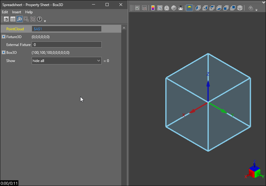
Quick Drop Region |
Clears the currently edited Box3D, Region3D, or Rectangle3D structure, and allows you to draw a new 3D box or 3D region of interest in the 3D viewer, as shown below.
Note: This button is enabled only when you edit the Box3D or Region3D structure of a function.
|
||||
|
|
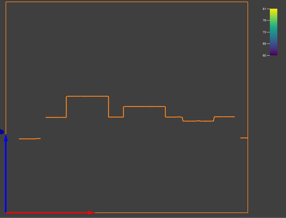
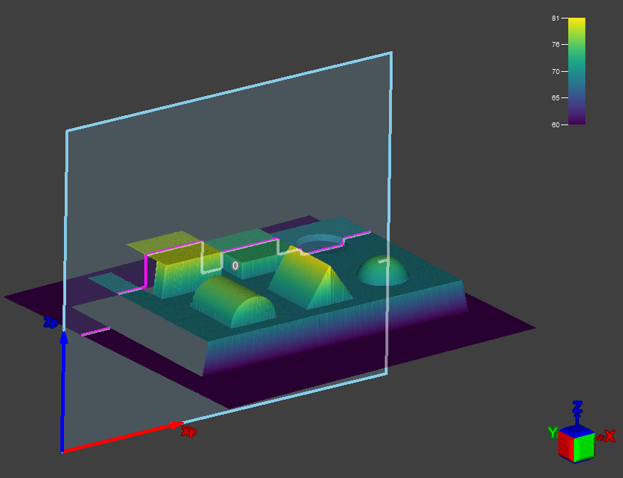
Profile View |
When you display a profile view on the 3D viewer (either by selecting a GetProfile cell, or any tool using this cell as reference), you can click on the Profile View button to change from full the Pointcloud view to the Profile view. In this case, the profile is automatically aligned with the screen and the pointcloud is hidden for a better visualization of the profile and the profile results. Click on the Profile View button to show the view from the profile direction:
Click on the button again to switch back to the default view. The default view shows the line of the profile view drawn into the point cloud.
|


 ) in the 3D viewer as shown below. This setting is disabled if the
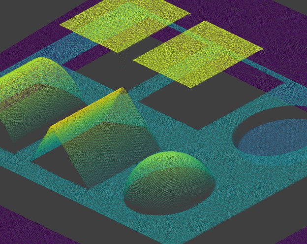
 button to enable perspective view, and click the
  button to switch back to the default orthographic view.