Refer to your Cognex CXP-12 hardware documentation for details on installing a CXP-12 frame grabber in your PC and connecting it to a CXP-12 camera using approved CXP-12 rated cabling.
Your VisionPro installation includes QuickBuild, a utility that allows you to configure an image source and analyze an acquired image with any number of Cognex vision tools. Use QuickBuild to learn which acquisition parameters function best for your CXP-12 camera as you develop your vision solution.
In addition, the CXP-12 camera supports an I/O cable and custom properties that allow you to respond to incoming hardware triggers and control external components such as lighting.
See the following sections for details on configuring CXP-12 acquisition and I/O settings:
Perform the following steps to acquire images from your CXP-12 camera using QuickBuild:
Double-click the QuickBuild icon on your Windows desktop or launch QuickBuild from the Windows Start menu:
By default, QuickBuild contains a single CogJob to pair an image source with all the vision tools that analyze the images it acquires:
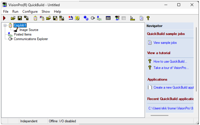
Double-click on CogJob1 to open the Job, and then double-click Image Source in CogJob1 to open its Image Source properties.
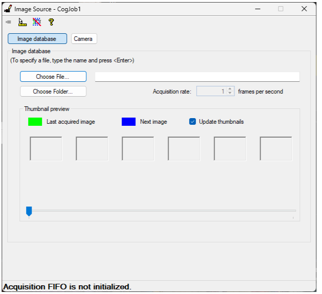
Select Camera to choose the image source:
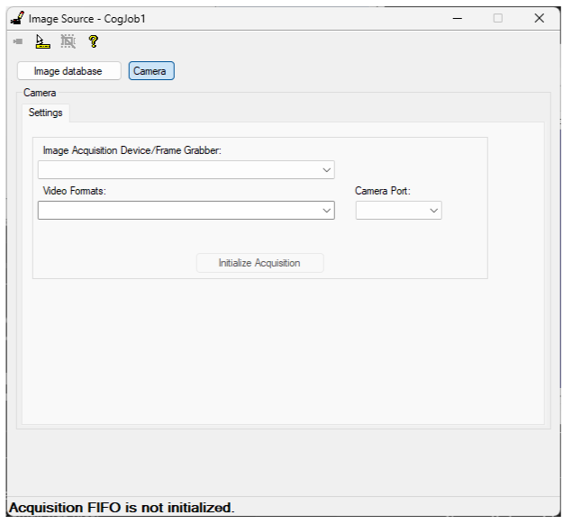
Select your CXP camera from the Image Acquisition Device/Frame Grabber pulldown:
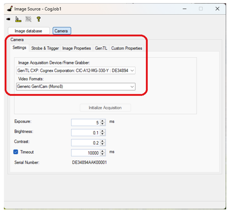
Use the following tabs to configure more settings for your CXP camera:
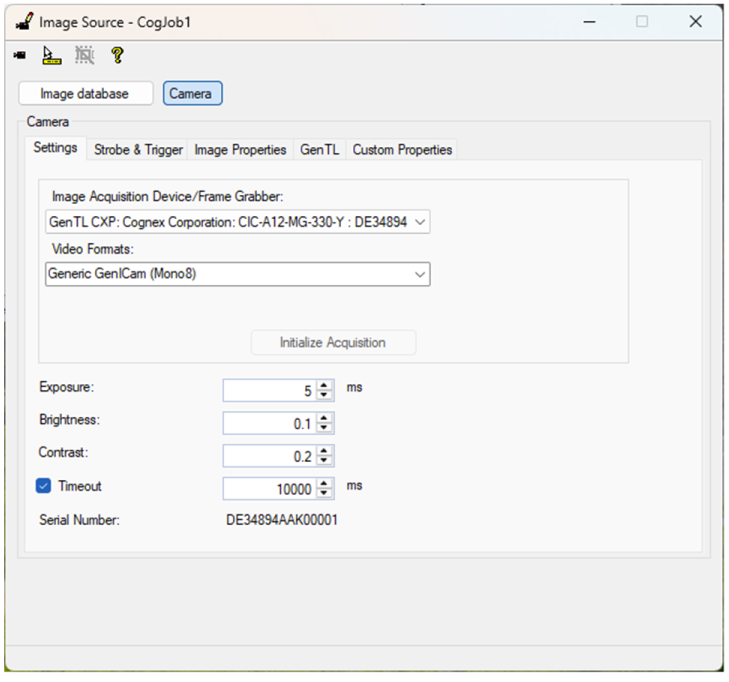
The Settings tab supports the following parameters:
| Parameter | Description |
| Exposure | Set an exposure time for each image acquisition. |
| Timeout | Set a maximum period the vision application waits for a completed acquisition after it detects the current trigger type. After this period the vision application reports an error. |
To start an image acquisition in QuickBuild, you must click the Run button for your CogJob. VisionPro acquires images based on the selected trigger mode:
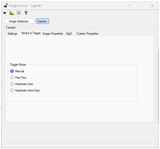
The Strobe and Trigger tab supports the following parameters:
| Trigger Mode | Description |
| Manual | Acquire a single image when you press the Run button for this CogJob. |
| Free Run | Gather images continuously and return an image for each completed acquisition. |
| Hardware Auto | Trigger an image acquisition when the application detects the correct transition on an external trigger line. You can determine whether the sensor uses a low-to-high or high-to-low transition to start profile acquisition. See the section Hardware Triggers for more information. |
| Hardware Semi-Auto | Trigger an image acquisition when you press Run and the application detects a transition on an external trigger line. In your Visual Studio application, using a Hardware Semi-Auto trigger configures the camera to begin an acquisition after you call StartAcquire prior to trigger detection. Your application must call CompleteAcquire to return the acquired image. See the section Hardware Triggers for more information on using hardware triggers. |
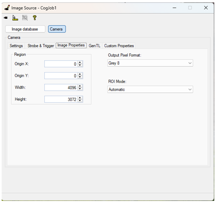
The Image Properties tab supports the following parameters:
| Image Property | Description |
| Origin X and Origin Y | Specify the X and Y sensor position for the first pixel of the image. |
| Width | Specify the width of the acquired image. The left-most pixel in the acquired image corresponds to the field Origin X. If you want a smaller image centered in the field of view you must adjust this Width value and the Origin X property. |
| Height | Specify the height of the acquired image. The top-most pixel in the acquired image corresponds to the field Origin Y. If you want a smaller image centered in the field of view you must adjust this Height value and the Origin Y property. |
| Output Pixel Format | Specify the pixel format the acquired image will be formatted into. Automatic allows QuickBuild to generate images with the appropriate output pixel format based on the type of camera you are using and the video format you chose on the Settings tab. |
| ROI Mode | Specify how the ROI of the image will be processed. Automatic allows QuickBuild to adjust the ROI of the image to be within the hardware limits of the camera. |
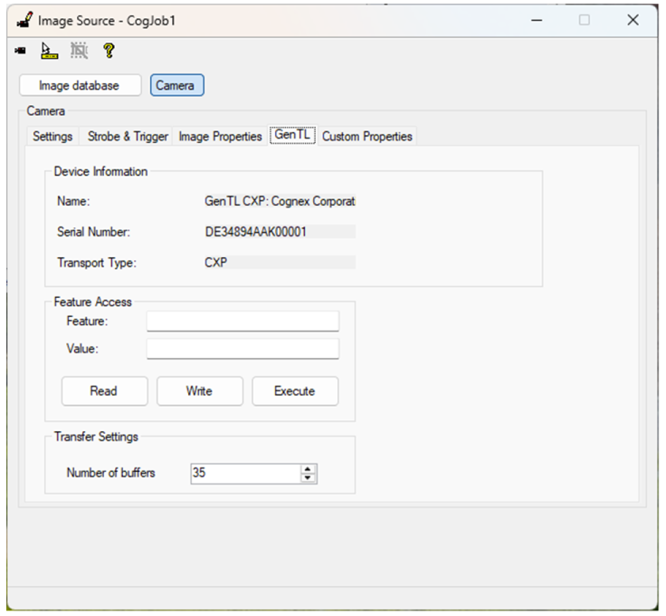
Use the GenTL tab to view basic information about the camera and modify various GenTL properties:
- To query the value of any GenTL feature, enter the name in the Feature field and click Read.
- Do not set features that are not explicitly supported.
- Avoid any features that appear listed in red in the Custom Properties tab.
The Custom Properties tab offers access to properties for controlling different aspects of the camera:
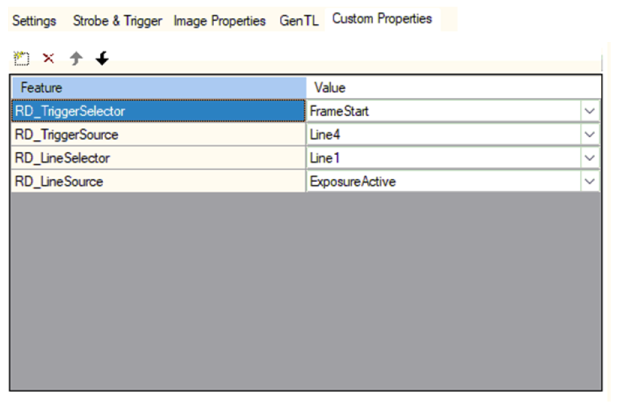
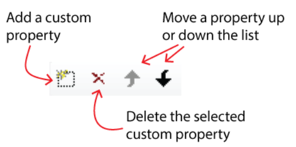
To manage the custom properties on this tab, use the button bar at the top of the table:
Refer to the following table for some example uses of custom properties:
| Purpose | Custom Property |
| Acquisition Framerate | Assign the custom property RD_AcquisitionFrameRateEnable a value of 1 to set a maximum frames-per-second the camera will acquire based on the value of RD_AcquisitionFrameRate. |
| Reversing the ROI | The custom properties RD_ReverseX and RD_ReverseY reverse the returned pixels on either the X-axis or Y-axis, respectively. |
| White Balancing Color Images | Set the custom property RD_BalanceWhiteAuto to On to calibrate the coloring of the image from the camera to balance the RGB channels based on the current image. To successfully white balance you need to fill the field of view of the camera with a piece of white printer paper and illuminate the image with a 6500K light source. |
This section contains the following subsections.
The CXP-12 camera supports I/O cables CCB-IO-HR12F-5 and CCB-IO-HR12F-10F to interact with connected devices such as hardware triggers and lighting. The following graphic represents pin numbering in the cable:
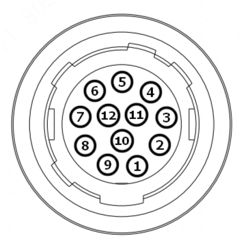
| Pin# | Signal | Description | Color | 1 | GND | Camera power ground | Black |
| 2 | +24VDC | +24V camera power supply | Red |
| 3 | not used | White/blue | |
| 4 | not used | White/Green | |
| 5 | Line3 | Opto-isolated input | Grey |
| 6 | Line4 | Opto-isolated input | White |
| 7 | Line5 | Opto-isolated input | Brown |
| 8 | Common In | Opto-isolated input ground, not to connect to power GND | Orange |
| 9 | Line0 | Opto-isolated input | Blue |
| 10 | Line1 | Opto-isolated input | Green |
| 11 | Line2 | Opto-isolated input | Purple |
| 12 | Common Out | Opto-isolated output ground, not to connect to the power GND | Yellow |
See the following sections for more information on using I/O lines:
To trigger an image acquisition from the CXP camera, use the pin I/O connector instead of the CXP frame grabber I/O interface.
Use the custom property RD_TriggerSelector to select FrameStart as the trigger you are assigning to an input since this will control the triggering used by Hardware Auto and Hardware Semi-Auto. The custom property RD_TriggerSource will then allow you to choose which input line to trigger from. The feature RD_TriggerDelay can be used to add a delay between when the hardware trigger comes in and when acquisition starts.
To utilize the camera output lines, select which line to work with using the RD_LineSelector feature. With a line selected you can then use the RD_LineSource feature to have that output fire when a chosen event occurs. For example, setting RD_LineSource to ExposureActive will output to the selected line for the duration that the camera is exposing its imager which is the primary way to set up a strobe light for acquisition. You can set the feature RD_LineInverter to True to cause the output to go from high to low when it is fired instead of low to high.