The Segment tool edit control provides a graphical user interface to the CogSegmentTool API, which you can use to divide an input image into foreground and background pixels. The tool generates information about foreground pixels that you can pass to other vision tools for analysis. See the topic Using a ViDiEL Segment Tool for more information.
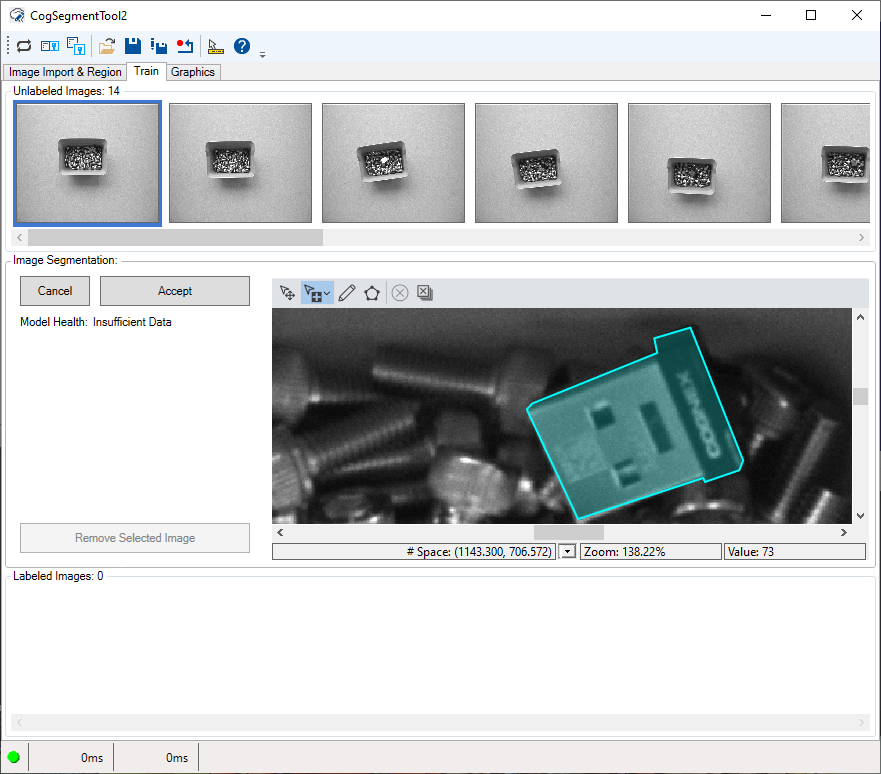
The following figure shows an example ViDiEL Segment tool edit control as you label foreground pixels in a training image:
The edit control offers the following features:
- A row of control buttons at the top provide access to the most common operations.
- A set of function tabs allows you to train this Segment tool to differentiate foreground pixels.
- An image display window shows acquired images and the output images a Segment tool can generate.
To include the edit control in your custom vision application, you must first add it to your Visual Studio .NET development environment. See the topic Adding Edit Controls to Visual Studio for more information.
See the following sections for more information:
The following table describes the function of each button in the button bar:
| Button | Description | Function |
 | Run | Examine the Current.InputImage and segment foreground pixels from background pixels. To run the tool you must have a trained Segment tool. |
 | Local image display | Open or close the local image display window. A Segment tool supports the following image buffers:
The edit control does not open the local image display by default, unless you choose the Graphics tab. |
 | Floating image display | Open one or more floating image windows, which support the same image buffers as the local image display window. |
 | Open | Open a VisionPro persistence (.vpp) file that contains a set of saved properties for this vision tool object type. VisionPro reports an error if you try to open a .vpp file for another object type. |
 | Save | Save the current properties of the vision tool to a VisionPro persistence (.vpp) file. The edit control allows you to choose between saving the vision tool with or without its image buffers and tool results. |
 | Save As | Save the current properties of the vision tool to a new VisionPro persistence (.vpp) file. |
 | Reset | Reset the vision tool to its default state. The tool gives you a choice between resetting to the default-constructed state, which is appropriate when you are using it in a Visual Studio.NET application, or its template-initialized state, which is appropriate for QuickBuild applications. |
 | Show Floating Results | Open a separate results window with the same contents as seen in the Results tab. |
 | Show ToolTips | Enable or disable the display of tooltips for individual items in the edit control. |
 | Help | Open this VisionPro online help file. |
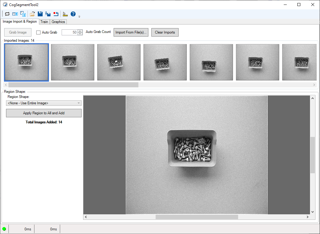
Use the Image Import & Region tab to acquire images from an image database or a connected camera:
See the topic Using a ViDiEL Segment Tool for details on using this tab to train a Segment tool.
See the following sections for more information:
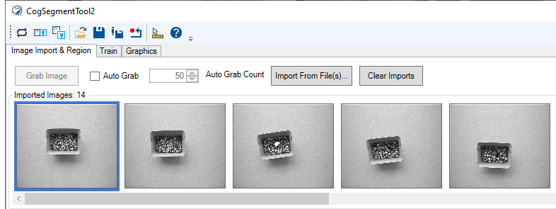
Imported images appear along the top of the tab:
Use the following options to import images from a file or from a connected camera:
| Button | Description |
| Grab Image | Import the image currently stored in the Current.InputImage buffer. |
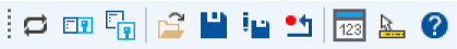
Auto Grab | Automatically import every image coming from an image source into the tool. With Auto Grab enabled, the Segment tool will not import more images than specified by Auto Grab Count. Note: Be aware that with Auto Grab enabled and your CogJob in continuous run mode, QuickBuild might experience an acquisition overrun and stop importing images. To prevent acquisition overruns, open the Image Source dialog box and decrease the Acquisition rate to 1 frame per second: 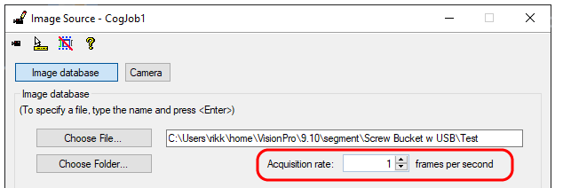 |
| Import From File | Import the image from a single .bmp, .png, .jpeg or all the images in an image-database file. The button does not remove existing imported images from the tool. |
| Clear Imports | Remove all imported images from the tool. |
Use the Region Shape to apply a affine rectangle to all the imported images:
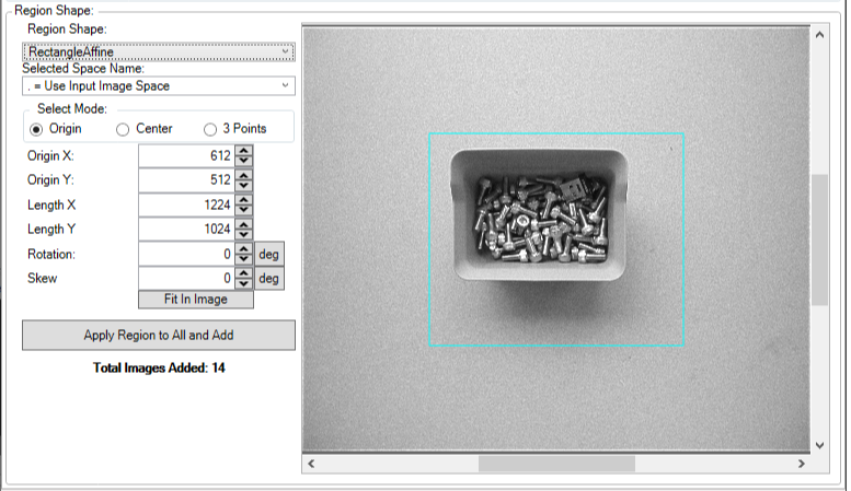
Click Apply Region to All and Add to transfer all the imported images to the Train tab.
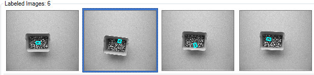
Use the Train tab to select any imported image, label the foreground pixels, and train the tool with this image.
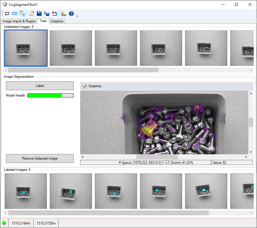
See the topic Using a ViDiEL Segment Tool for details on using this tab to train a Segment tool. The tab supports a set of tools for highlighting foreground pixels:
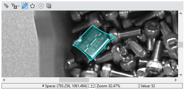
Check Graphics to enable a heatmap over the selected image to represent pixels the tool considers to be candidates for foreground pixels.
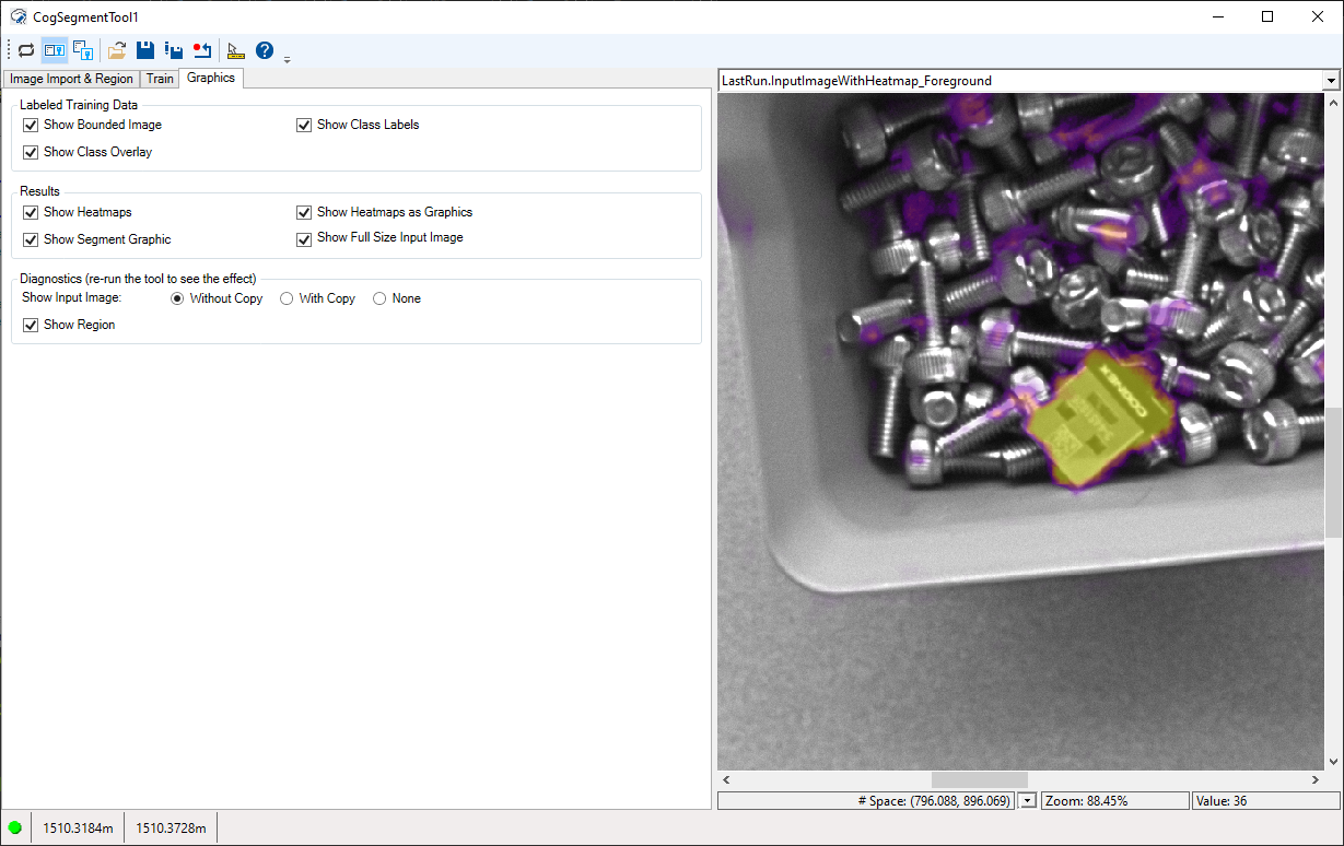
Use the Graphics tab to enable/disable graphics that appear in the images on the Train tab and in the LastRun images:
The following options create an image record for any selected labeled image on the Train tab:
These options have no effect if you do not have a labeled image selected.
| Show Bounded Image | Included the bounded image of the currently selected Labeled image. |
| Show Class Overlay | Include a single graphic overlay that colors each bounded image pixel according to the labeled assignments of the currently selected Labeled image. |
| Show Class Labels | Create a mask image for each shape assignment in the labeled image. |
Enable or disable any of the following options for viewing the results the Segment tool generates:
| Show Heatmaps | Include a heatmap image for the foreground pixels. |
| Show Segment Graphic | Highlight the foreground pixels in the LastRun.InputImage. |
| Show Heatmaps as Graphics | Include a LastRun.InputImage highlighting the foreground pixels. |
| Show Full Size Input Image | Include the full sized Current.InputImage. |
The Without Copy, With Copy, and None options determine whether or not the input image is recorded as part of the diagnostic record; and whether the image is copied to the record or saved in the record as a reference.