Your processor must support the AVX2 instruction set for any Cognex 3D operations.
This release adds the CPUCanExecute3D method to return True if the processor in your computer is capable of executing Cognex 3D operations. Otherwise the method returns False. Use the CPUCanExecute3D method to verify any computer you use to create or deploy your application can perform 3D operations.
This topic contains the following sections.
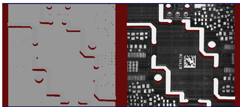
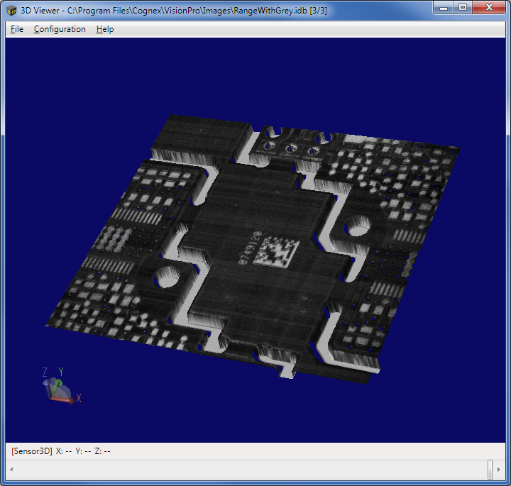
A RangeWithGrey image is a combined image consisting of a range image and a 16-bit greyscale image acquired at the same time using a displacement sensor. The following image shows a RangeWithGrey image of an electronic component.
Enabling High Dynamic Range changes the range of greyscale values that appear in the greyscale part of the acquired RangeWithGrey image.
For information on setting up acquisition with your displacement sensor, see the Getting Started topic. For detailed information on range image acquisition, see the General 3D Sensor Acquisition topic. For advanced range image acquisition details, including coordinate spaces related to range images, see the [7cfa53df-c631-4ecc-8d2f-7934a074d658] topic.
Use the Cog3DRangeGreySplitterScript CogToolBlock to split a RangeWithGrey image into separate 3D range and 16-bit greyscale images. VisionPro contains a sample application that demonstrates its use.
Find the Cog3DRangeGreySplitterScript CogToolBlock under 3D Tools in the QuickBuild tool palette. A new Cog3DRangeGreySplitterScript CogToolBlock appears as shown:
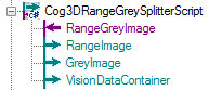
In addition to generating a CogImage16Range and CogImage16Grey, the tool block creates a CogVisionDataContainer for use with vision tools such as the CogVisionDataStitch tool or the Cog3DVisionDataRerender tool.
If the input image is not a range image or if the input image is null, the output terminals will be set to null, the tool's result will be set to "Error", and the tool's error message will be set to "Input image is null, or input image type is not supported".
If the width of the input image is odd, the output terminals will be set to null, the tool's result will be set to "Error", and the tool's error message will be set to "The width of the image is odd indicating that the image is not a combined image."
| Cognex recommends you do not change the name of any terminal. The names are used by the CogToolBlock script and if you must update the script if you change the name of any terminal. |
The Cog3DRangeGreySplitterScript CogToolBlock does not support an API. Programmatic users can examine the script within the tool block to recreate the functionality. The tool block uses the CogCopyRegion class to produce the range image and the grey image as follows:
- Two regions are created: one for the left half of the image (range region) and one for the right half of the image (grey region).
- The 16-bit greyscale image is extracted from the input range image.
- The Execute method on the CogCopyRegion operator is called once using the input range image and the range region to produce the output range image.
- The Execute method on the CogCopyRegion operator is called a second time using the 16-bit grey image and the grey region to produce the output grey image.
- A CogVisionDataContainer object is created, and both the range and the grey images are added to the container object.