See the following sections to get started with an L68 series sensor:
The L68 uses the CCB-PWRIO-XX cable with the following wiring assignment:
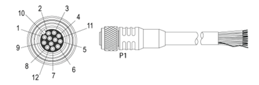
| Pin# | L68 Signal name | Wire Color |
| 1 | GND | Yellow |
| 2 | +24VDC | White/Yellow |
| 3 | TRIGGER | Brown |
| 4 | not used | White/Brown |
| 5 | not used | Violet |
| 6 | ENCODER B- | White/Violet |
| 7 | ENCODER A+ | Red |
| 8 | LASER ENABLED GND | Black |
| 9 | LASER ENABLED +24VDC | Green |
| 10 | not used | Orange |
| 11 | ENCODER B+ | Blue |
| 12 | ENCODER A- | Grey |
Note: The 3D-L68 supports only differential quadrature encoders following the RS422 specification, and does not support single-ended encoding and single-channel encoders.
The 3D-L68 does not support the Dynamic Host Configuration Protocol (DHCP), and arrives factory programmed with the following IP address and subnet mask:
| IP Address | 192.168.178.200 |
| Subnet Mask | 255.255.255.0 |
To communicate to the sensor, you must configure the host Ethernet network adapter to 192.168.178.X and subnet mask 255.255.255.0. See the Microsoft Change TCP/IP Settings page for more instructions on how to configure these settings based on your version of Windows.
Once on the same network as the sensor you can either work with the sensor immediately or change the sensor’s IP using the L68_Configuration_Tool utility as shown:
- Open a command line window and navigate to the %VPRO_ROOT%\bin directory.
Enter the following command: L68_Configuration_Tool.exe
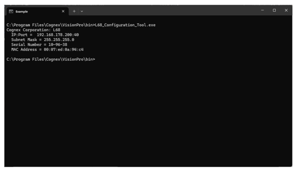
- Confirm that the MAC address of the sensor you wish to change matches the MAC address of label on the sensor.
Enter the following command: L68_Configuration_Tool.exe -t <IP address of target sensor> -n <new IP address of the sensor> -s <new subnet mask of the sensor>.
Note: The utility cannot discover sensors on external networks. If you choose to change the sensor to a non-default network you will need to track that new network to easily configure the IP again.
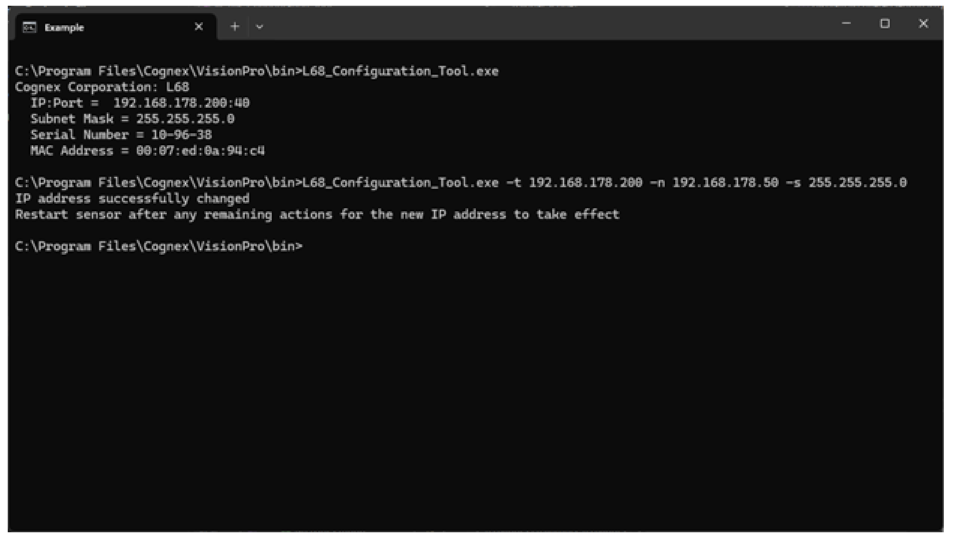
- Manually power off the sensor and then power it back on.
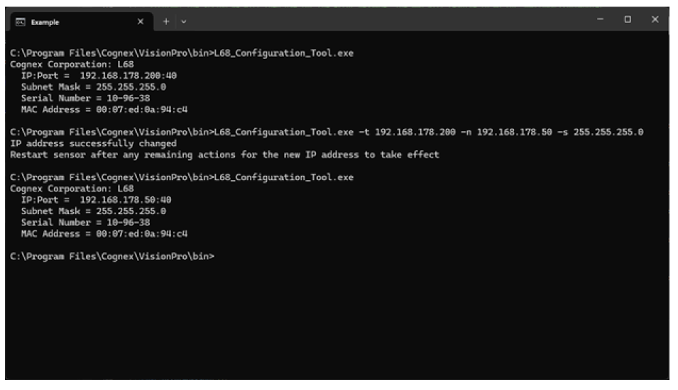
- If on the same network enter the following command: L68_Configuration_Tool.exe.
If not on the same network:
- Configure the connected network adapter to the new network with the previous instructions.
- Enter the following command: L68_Configuration_Tool.exe.
Confirm the sensor reports the new IP address.
The L68 uses custom properties to configure the device. The following is a list of the available custom properties:
| CameraMode | Write/Read | Sets the type of data being acquired. IntensityImage for setting the ROI or Range for acquiring 3D data | Default: IntensityWithROI |
| ScanLengthInPixels | Write/Read | Sets the number of rows to acquire in a Range image | Default: 1000 |
| XScale | Write/Read | Specifies the physical size of range image pixels in the X direction (in mm/pixel) | Default: 0.006300 |
| YScale | Write/Read | Specifies the physical size of range image pixels in the Y direction (in mm/pixel). Set this value to match the distance your motion system moves between each image row. | Default: 0.100000 |
| ZScale | Write/Read | Specifies the physical size in the Z direction corresponding to one-grey-level change in the value of a range image pixel (in mm/grey-level) | Default: 0.001050 |
| MotionInput | Write/Read | Specifies whether acquisition is performed using a physical encoder, a simulated encoder, or as fast as possible (without any encoder) | Default: Encoderless |
| SimulatedEncoderFrequency | Write/Read | If MotionInput is set to SimulatedEncoder, this value specifies the frequency of the simulated encoder (in Hz) | Default: 200 |
| EncoderStepsPerLine | Write/Read | If MotionInput is set to PhysicalEncoder, this value specifies how many encoder steps occur between each line of the acquired Range image. | Default: 1 |
| IgnoreTooFastEncoder | Write/Read | Sets whether IsTooFastEncoder acqfailure can be generated due to a line overrun situation. Default is true (line overruns will not be reported) | Default: True |
| StartAcqOnEncoderCount | Write/Read | Sets the number of encoder counts to wait before acquisition starts. This property only applies when the MotionInput is set to PhysicalEncoder | Default: 0 |
| PositiveEncoderDirection | Write/Read | Specifies the scene motion that causes the encoder to generate positive-direction pulses. Set this value to LensToLaser if motion in that direction generates positive encoder pulses; otherwise, set this value to LaserToLens. | Default: LensToLaser |
| AcquireDirection | Write/Read | Specifies the scene motion for the next image acquisition. If MotionInput is set to PhysicalEncoder only motion in this direction will cause image data to be acquired. | Default: LensToLaser |
| AutoCorrectPixelRowOrder | Write/Read | Specifies whether to automatically set the row-order of the acquired image to match the actual appearance of the scene. If this value is set to False, images acquired the LaserToLens direction will appear to be mirrored top-to-bottom. | Default: True |
| HighDynamicRange | Write/Read | When true, the camera uses two different exposures to increase the dynamic range of the visible laser line. One exposure will be the requested value, and the other will be one-tenth of that. This is useful if your scene contains both dark and highly reflective regions. It also reduces the maximum line rate. | Default: False |
| HighDynamicRangeMergeMode | Write/Read | When HighDynamicRange is enabled, this value specifies whether each line of the range image is created by merging the last two exposures, or by using only the last exposure. | Default: RollingMerge |
| Gain | Write/Read | Specifies the gain level for the acquisition. Each increase in level makes the laser line brighter without increasing the exposure time of the acquisition. It also increases the amount of noise in the image. | Default: Off |
| LaserLineIntensityThreshold | Write/Read | Specifies the minimum intensity required for a pixel to be recognized as part of the laser line. Lowering this value makes laser detection more sensitive but also more susceptible to noise. | Default: 40 |
| PeakDetectionMode | Write/Read | Specifies which laser line to use in cases where multiple lines can appear. For example, this can occur when imaging transparent objects | Default: MaxIntensity |
| LaserMode | Write/Read | Reads or sets the mode of the laser. Default is Strobed. Laser is on when an image is acquired. “Off" is intended for setup and diagnostic purposes only. | Default: Stobed |
| BinningHorizontal | Write/Read | Specifies whether to reduce the horizontal (X-axis) resolution of the camera, to increase speed. Choosing 'X2' will average together pairs of neighboring columns in the intensity image, resulting in a smaller image that can be processed more quickly. | Default: Off |
| BinningVertical | Write/Read | Specifies whether to reduce the vertical (Z-axis) resolution of the camera, to increase speed. Choosing 'X2' will average together pairs of neighboring rows in the intensity image, resulting in a smaller image that can be processed more quickly. | Default: Off |
| AdvancedReflectionFilterMode | Write/Read | Specifies whether to filter out (i.e. ignore) pixels from the laser line that are inconsistent with the pixels in neighboring image columns. LowHeightVariance mode will work best with smoothly varying surfaces. HighHeightVariance will select points which fall in a band around nearest neighbors and will work best for sudden, discontinuous changes in height. | Default: Off |
| ROIXIncrement | Read Only | Shows the numeric base that the pixel values of ROI parameters on the X axis must be multiples of or else be rounded. | |
| ROIYIncrement | Read Only | Shows the numeric base that the pixel values of ROI parameters on the Y axis must be multiples of or else be rounded. | |
| IntensityImageWidth | Read Only | Shows the width an Intensity or IntensityWithROI image will be. | |
| IntensityImageHeight | Read Only | Shows the height an Intensity or IntensityWithROI image will be. | |
| RangeImageWidth | Read Only | Shows the width of the resulting Range image based on the current scaling properties. | |
| LineFrequency | Read Only | Shows the current line frequency. This value will internally be refreshed during acquisition. | |
| IsTooFastEncoder | Read Only | Shows if a line overrun happened during the current acquisition. | |
| EncoderStepFrequency | Read Only | Shows the actual detected frequency of the configured encoder steps. | |
| MaximumLineFrequency | Read Only | Shows the largest line frequency that can be achieved by the sensor in its current configuration. This value is updated at the beginning of an acquisition. | |
| SensorTemperature | Read Only | Shows the internal sensor temperature in degrees Celsius. | |
| FirmwareVersion | Read Only | Shows the actual Firmware version | |
| IPAddress | Read Only | Shows the IP address of the sensor | |
| SubnetMask | Read Only | Shows the subnet mask of the sensor | |
| DefaultGateway | Read Only | Shows the default gateway of the sensor | |
| MacAddress | Read Only | Shows the MAC address of the sensor | |
| SerialNumber | Read Only | Shows the serial number of the sensor |
Enable HighDynamicRange and allow the camera to use multiple exposures to increase the dynamic range, which can be useful when the laser line passes over regions that can be both dark and highly reflective. Enabling HighDynamicRange will reduce the MaximumLineFrequency.
Use HighDynamicRange to change the way your vision application processes multiple exposures:
RollingMerge
Acquires a line alternating between an exposure one tenth the specified exposure and the specified exposure, and uses the current line and the previous line to find points in each column of the image.
If the sensor identifies a point in the same column between both exposures, it uses the value of the lower exposure.
NoMerge
Acquires a line alternating between an exposure one tenth the specified exposure and the specified exposure, generating an output image that collates all lines with no comparison between the alternating exposure.
This results in an image where every pair of lines is one taken at the one tenth exposure and followed immediately by one taken at the full exposure.
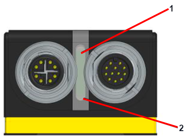
| 1. Boot Status LED or Connection LED | Blinking Frequency | Indication |
| WHITE | Slow blinking | Booting state on power-up |
| WHITE | Fast blinking | Boot state (during firmware update) |
| GREEN | Slow blinking | Boot complete, "Waiting for connection" state |
| GREEN | Fast blinking | Data acquisition in progress |
| GREEN | Solid | Connection between host computer and sensor has been established |
| RED | Blinking | Fault detected during self-test mode |
| RED | Solid | Error state |
| YELLOW | Blinking | Self-Test Mode (powering sensor without Ethernet cable connected) |
| 2. Power LED | Blinking Frequency | Indication |
| ORANGE | Solid | 24V power supply detected |