Use a DSMax 3D sensor to generate 3D range images of objects under inspection. The DSMax 3D sensor uses the CoaXPress communication protocol to communicate with a DSMax frame grabber for data transfer and can acquire 3D images at a higher rate than the Cognex DS1000 or DS900 series sensors. A DSMax 3D sensor can be configured to acquire a 3D range image, a combined 3D range image and greyscale image, or a simple intensity image showing the shape of the laser line as seen in the field of view.
Differential encoder signals as well as differential trigger signals are sent to the vision application through the I/O connections on the DSMax frame grabber.
See the following topics for more information on 3D range images:
This topic contains the following sections.
To use your DSMax sensor, perform the following steps:
Install the DSMax CXP frame grabber in your PC.
Refer to your DSMax frame grabber hardware documentation for details.
Mount your DSMax CXP sensor and connect it to your DSMax frame grabber using the provided CoaXPress cables.
Refer to your DSMax sensor hardware documentation for details.
Install your VisionPro software.
This topic describes how to acquire images using the VisionPro QuickBuild interface.
To configure a new image acquisition using a DSMax sensor in QuickBuild, perform the following steps:
Double-click the QuickBuild icon on the Windows desktop or launch QuickBuild from the Windows Start menu.
QuickBuild launches and appears as shown:
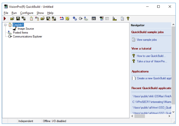
By default QuickBuild contains a single CogJob to pair an image source and all the vision tools that will analyze the images from that source.
Double-click on Image Source for CogJob1 to open the Image Source interface:
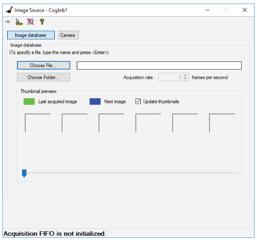
Choose Camera to display a Settings tab where you can choose the image acquisition source:
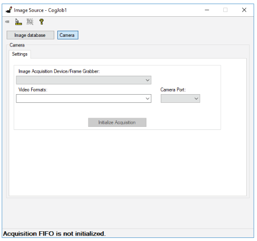
From the Image Acquisition Device/Frame Grabber: pulldown, select your DSMax 3D sensor and click Initialize Acquisition.
The Image Source interface adds a series of tabs to fully configure the acquisition properties of a DSMax sensor:
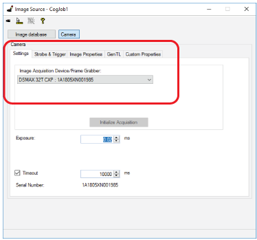
Use the following tabs to configure your DSMax sensor:
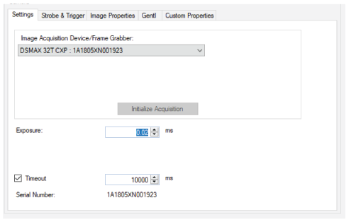
The Settings tab supports the following parameters:
| Parameter | Description |
Exposure | Set an exposure time for each image acquisition of a laser profile. A DSMax sensor typically works with exposures in the range of 0.05 to 0.3 milliseconds. Higher values allow the camera to collect more information about the laser line reflected from the surface of the object under inspection and can be used for surfaces that are less reflective. Experiment to find the best value for your application. |
Timeout | Set a maximum period the vision application waits for a completed acquisition after it detects the current trigger type. After this period the vision application reports an error. A Timeout is typically used for handling unexpected issues with the production environment (motion system, encoder). Experiment to find the best value for your application. |
To start an image acquisition in QuickBuild, you must click the Run button for your CogJob. VisionPro acquires images based on the selected trigger mode:
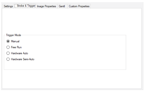
| Trigger Mode | Description |
Manual |
|
Free Run |
|
Hardware Auto |
|
Hardware Semi-Auto |
See the section Hardware Triggers for more information on using hardware triggers. |
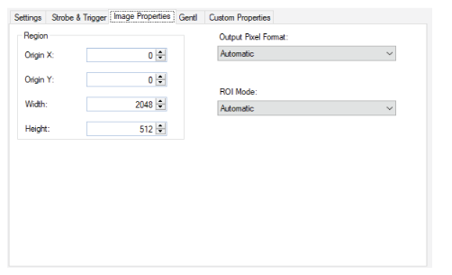
Some image-property parameters are set in this Image Properties tab while others must be set using the custom properties the DSMax sensor supports.
| Image Property | Description |
Origin X and Origin Y | VisionPro ignores any settings you configure. Use the X Origin and Y Origin instead. See the custom properties section for more information. |
Width | Specify the width of the rendered image. The left-most pixel in the rendered image corresponds to the custom property X Origin. If you want a smaller image centered in the field of view you must adjust this Width value and the X Origin custom proprety. |
Height | Specify the number of profiles the DSMax sensor acquires for a single image:
|
| Output Pixel Format and ROI Mode | Cognex strongly recommends you keep both parameters at Automatic. While these parameters can be modified for cameras acquiring 2D images, the Automatic setting works for most applications that use a Cognex 3D sensor. |
The GenTL tab offers access to various GenTL features:
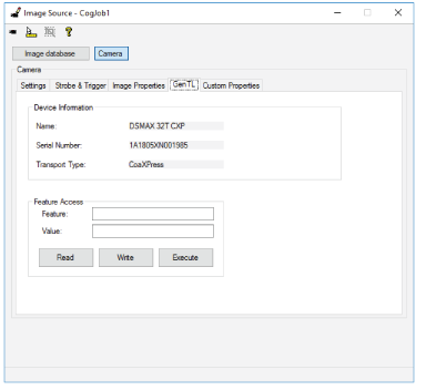
Use the GenTL tab to view basic information about the sensor and modify various GenTL properties.
- To query the value of any GenTL feature, enter the name in the Feature field and click Read.
- Do not set features that are not explicitly supported.
- Avoid any features that appear listed in red in the Custom Properties tab.
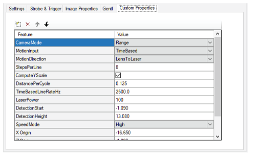
The Custom Properties tab offers access to properties for controlling different aspects of the 3D sensor, such as the laser, the encoder you are using for motion detection, and the type of image you want the sensor to generate, and more:
To manage the custom properties on this tab, use the button bar at the top of the table:

Use custom properties to control the following:
- Image Type
- Hardware Triggers
- Encoder Features
- Laser Power
- Speed Mode
- Range Image Rendering
- Detection Zone
- High Dynamic Range (HDR) Mode
- Miscellaneous Features
Image Type
Use the CameraMode property to determine the type of image the DSMax sensor returns:
- Range (default): The sensor generates 3D range images at a fixed line rate or based on an encoder depending on the MotionInput setting.
RangeWithGrey: The sensor generates a combined image consisting of a range image and a 16-bit greyscale image acquired at the same time.
Be aware that RangeWithGrey acquisitions require more processing time and the images consume twice as much memory in your PC.
Intensity: The sensor generates an image showing the laser line viewable from the camera in the sensor.
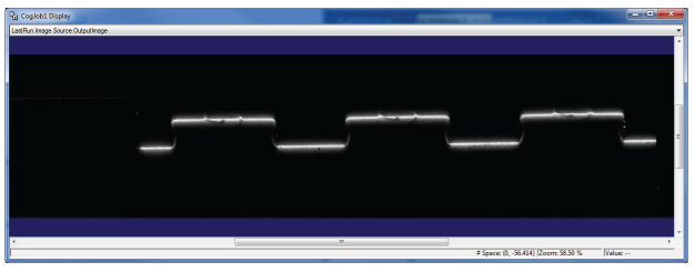
Capturing an intensity image can be helpful to know if your laser is over-exposed or under-exposed based on your settings for Exposure. In addition, you do not need to supply a hardware trigger to acquire an intensity image. Perform the following steps to capture an intensity image.
- Set CameraMode to Intensity.
- Place the desired object under the laser of the DSMax sensor.
- Run the QuickBuild job that uses DSMax sensor as the image source.
The frame rate will be much lower than you would otherwise expect based on the current Exposure setting. Be aware that the sensor runs at a fixed maximum rate which can slow for longer exposures.
Hardware Triggers
By default VisionPro requires a low-to-high transition to start profile acquisition. Be aware of certain hardware trigger behavior with the DSMax sensor
- Your vision application responds to hardware triggers based on your settings in the Strobe and Triggers tab.
- The Custom Properties tab supports the IF_CM_HW_Trigger_Polarity option to select between low-to-high or high-to-low transition to start profile acquisition.
- If the trigger signal starts in a high state (IF_CM_HW_Trigger_Polarity: Active High), it must first transition to low and then back to high to start acquisition.
Acquisition will continue until the trigger signal undergoes a high-to-low transition.
- If the trigger signal goes low before the number of profiles requested by the user through the ROI height is reached, acquisition will stop immediately and the number of profiles acquired will be returned to the user in a range image.
- If the number of profiles requested by the user via the ROI height is reached before the trigger signal goes low, the user will receive a range image containing the requested number of profiles and (if auto trigger model is in use) acquisition will continue and subsequent profiles will be put into the next range image.
Refer to the following tables depending on how you set the custom property IF_CM_HW_Trigger_Polarity.
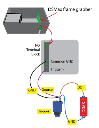
For a 0V-5V or 0-24V input set IF_CM_HW_Trigger_Polarity to Active_Low and leave Trigger+ floating:
| Input volt @ Trigger + | Input volt @ Trigger - | Trigger Logic Level to FPGA | Trigger Status |
|---|---|---|---|
| Unconnected (Weak 2.5V) | 5V / 24V | ‘0’ | Enabled |
| Unconnected (Weak 2.5V) | 0V | ‘1’ | Disabled |
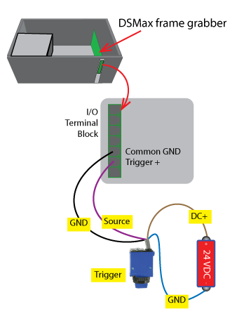
For 0V-24V input you can set IF_CM_HW_Trigger_Polarity to Active_High and leave Trigger- floating:
| Input volt @ Trigger + | Input volt @ Trigger - | Trigger Logic Level to FPGA | Trigger Status |
|---|---|---|---|
| 24V | Unconnected (Weak 5V) | ‘1’ | Enabled |
| 0V | Unconnected (Weak 5V) | ‘0’ | Disabled |
Encoder Features
Refer to the following wiring diagrams for connecting a differential encoder and a single-channel encoder to your DSMax frame grabber:
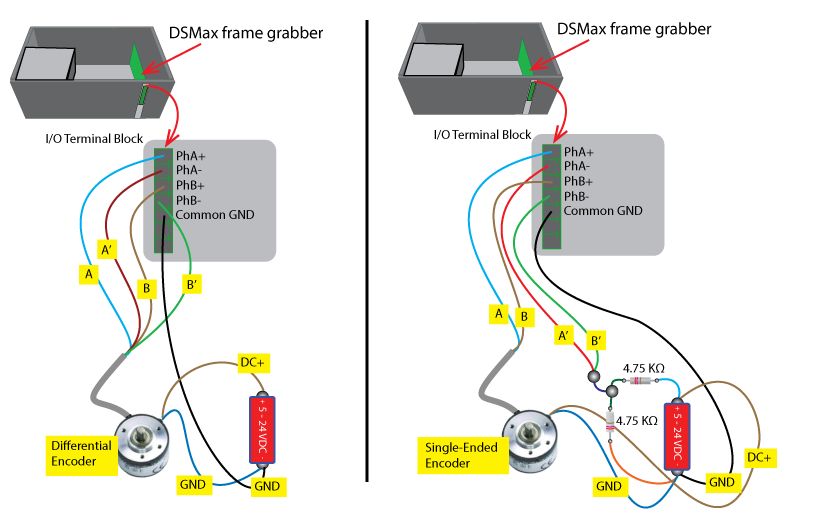
Use the following custom properties to manage the encoder attached to your motion system or to specify a fixed-profile frequency for acquiring images without an encoder, which can be helpful for developing and testing your vision application:
MotionInput: A value to control whether the DSMax sensor acquires images using a physical encoder or through a fixed-profile frequency:
- QuadratureEncoder: Use a physical quadrature encoder where the square wave frequency indicates the speed of shaft rotation, whereas the A-B phase relationship indicates the direction of rotation.
SingleChannel: Use a single-channel encoder that cannot indicate the direction of motion.
SingleChannel uses Phase A and ignores Phase B of the encoder input, and can be used with a quadrature encoder to make it function as a (directionless) single-channel encoder.
- TimeBased: Use a simulated encoder where the custom property TimeBasedLineRate sets the profile rate.
- Manual: Internal use only.
MotionDirection: An enumeration which indicates the direction the object is travelling under the sensor. This property as well as IF_CM_Encoder_Phase_Dir must be configured correctly to get accurate data. Set the property to either value:
- LensToLaser: The objects travels from the lens to the laser as it passes within view of the sensor.
- LaserToLens: The objects travels from the laser to the lends as it passes within view of the sensor.
- TimeBasedLineRate: When MotionInput is set to TimeBased, this feature sets the profile frequency in Hz.
- StepsPerLine: Sets the number of encoder ticks per profile.
DistancePerCycle: Sets the distance moved along the Y-axis for each cycle (4 ticks) of the encoder.
VisionPro uses this value combined with StepsPerLine to compute the distance along the Y-axis between each profile acquired by the sensor as:
StepsPerLine * DistancePerCycle / 4
If you do not set this value correctly, the 3D range image will not correctly reflect the actual dimensions of the object.
- ComputeYScale: If set to True (default), the value of Y Scale is set to StepsPerLine * DistancePerCycle / 4. If False, the value of Y Scale is not overwritten. Note that if ComputeYScale is set True and then False, the value previously set in Y Scale will be lost.
- IgnoreEncoderOverrun: If set to True, encoder overrun errors detected by the hardware are not converted to acquisition errors. When an encoder overrun does occur and is ignored, the acquired image may appear "compressed" on the Y axis due to missing profile data that would have been acquired if the line rate was within limits.
Your vision application should not access any of the following custom properties unless you set MotionInput to Manual:
- IF_CM_Encoder_Mode: Set by VisionPro based on the MotionInput setting.
- IF_CM_Count_Per_Scan: Divides down encoder pulses used to trigger each profile. The value written by VisionPro will be either StepsPerLine or a value calculated from TimeBasedLineRate.
- IF_CM_Scan_Dir: Set based on MotionDirection setting.
- IF_CM_Scan_Dir_Hysteresis: Used to control the number of encoder steps that automatic encoder direction determination takes before it will assume that the direction of travel has changed.
The Custom Properties tab also gives you access to the following properties:
- IF_CM_Encoder_Scale: Set the encoder resolution. Cognex highly recommends to leave this set to Clock_Mode_4x which provides the best resolution. Changing it will require a corresponding change to DistancePerCycle to maintain accurate Y axis measurements.
- IF_CM_Encoder_Phase_Dir: Controls the the direction in which the encoder counts up, either PhA_PhB or PhB_PhA. This must be set so that the encoder count increments in the lens to laser direction.
- IF_CM_Trigger_Source: When Hardware Auto or Semi trigger model is selected, this feature controls whether the trigger is an external signal (External) or an internal signal created by the encoder (Encoder). Profiles are acquired when both the trigger is active and motion is in the desired direction as indicated by IF_CM_Scan_Dir. Hardware signals into TRIGGER+ and TRIGGER- are ignored when IF_CM_Trigger_Source is in Encoder mode.
- IF_CM_Encoder_Count: The current encoder position. Note that the encoder position is tracked whether or not acquisition is active. This is useful when using encoder triggered acquisition on a motion stage, as the stage can be returned to its original position between acquires and the frame grabber will still track the motion, meaning the start and end encoder count positions won't move if there is motion between acquires
- IF_CM_Encoder_Count_Reset: Resets the encoder count to 0. Use this to set the current position as the reference position when using encoder triggered acquisition.
IF_CM_Encoder_Count_LB, IF_CM_Encoder_Count_UB:
- These features only apply when IF_CM_Trigger_Source is set to Encoder.
- When IF_CM_Trigger_Source is Encoder, the trigger is active whenever IF_CM_Encoder_Count is within these bounds.
- When MotionDirection is LensToLaser, acquisition starts at the lower bound and ends at the upper bound. When MotionDirection is LaserToLens, acquisition starts at the upper bound and ends at the lower bound
Laser Power
The Custom Properties tab offers the LaserPower property, which you can set to a value between 0 and 255 depending on the reflective qualities of the object under inspection. The laser will be turned on and off automatically for each image acquisition.
The tab also allows you to add and configure the LaserMode property with either of the following settings:
The default Strobed provides the automatic on and off control.
Be aware there is a significant delay imposed on the first acquisition to allow the laser to come up to full power in Strobedmode.
The value Manual allows you to control the laser by writing directly to the property RD_LaserPower property with a value between 0 and 255.
In Manual mode the laser will not be turned on and off automatically for each image acquisition, but the laser will turn off if the VisionPro application exits normally.
VisionPro supports Manual mode if the delay imposed by Strobed is not acceptable for your vision application.
Speed Mode
The Custom Properties tab offers the SpeedMode setting that balances laser detection against the maximum speed at which the sensor can acquire laser profiles. Refer to the following list for the maximum number of acquisitions possible depending on your setting for SpeedMode:
- High: 20.0 kHz for exposures up to 46 microseconds
- Medium: 12.5 kHz for exposures up to 79 microseconds
- MediumLow: 10.1 kHz for exposures up to 46 microseconds
- Low: 2.5 kHz for exposures up to about 400 microseconds
Cognex recommends you use the slowest setting for SpeedMode that solves the application and the highest Exposure setting. Specifically:
Does the High option with Exposure of 46 microseconds detect the darkest areas?
If yes, then use the High option.
Does the Medium option with Exposure of 79 microseconds detect the darkest areas?
If yes, then use the Medium option.
- Use Low option with an Exposure that detects the darkest areas of the image.
After choosing a setting for SpeedMode, if the brightest parts of the laser line appear saturated in your images, enable High Dynamic Range mode.
Range Image Rendering
Use the following custom properties to control the rendering of a 3D range image:
X Origin, Y Origin, and Z Origin: Specify offsets to the origin of the range image rendering coordinates:
- X = 0 corresponds to the center of the field of view
- Y = 0 corresponds to the center of the first acquired profile along the axis of motion. Individual data points in the first profile will generally have a slightly non-zero Y value due to accounting for the characteristics of the laser plane.
Z = 0 corresponds to the 0 reference of the DSMax sensor, which is approximately the furthest distance from the camera that a sensor is designed to view.
By default, Z Origin will be slightly negative to ensure all data generated by the sensor is captured, since most sensors can generated small negative Z values in the sensor coordinate system.
- X Scale: Specifies the distance between each pixel in each row of the 3D range image, in mm.
Y Scale: Specifies the distance between each pixel in each column of the 3D range image, in mm.
If ComputeYScale is set to True, this value will be overwritten when the hardware is configured for acquisition.
Be aware that if Y Scale is on the Custom Properties tab, the value displayed there will not be updated to reflect the new computed value when ComputeYScale is set to True since the table reflects what the feature will be to in the future and does not reflect the current value of the property.
- Z Scale: Specifies the distance between each pixel along the z-axis of the 3D range image, in mm.
Detection Zone
The DSMax sensor allows you to specify a limited range of the Z-axis where the sensor will locate the laser stripe in each profile. Use a detection zone to eliminate unwanted reflections from contributing to your 3D range images. For example, vision applications that use a 3D sensor to perform measurements on a glass surface can use a detection zone to ignore reflections that the vision application can ignore.
- The sensor must use a minimum of 16 rows for laser detection, and VisionPro will automatically adjust any detection zone settings to get a minimum of 16 rows. VisionPro attempts to keep the detection zone centered on the same sensor row that you originally configured.
- If you specify a detection zone entirely outside the measurement range, the acquisition fails and VisionPro will generate an error indicating whether the zone is above or below the measurement range.
Use the following parameters to control a detection zone:
DetectionStart: Set the bottom of the detection zone, in mm, relative to the same Z=0 reference as specified by Z Origin.
VisionPro assigns the same setting to DetectionStart and Z Origin by default. Larger values for DetectionStart represent distances closer to the sensor.
- DetectionHeight: Set the height of the detection zone, in mm, starting at a height defined by DetectionStart.
High Dynamic Range (HDR) Mode
Use the custom property RD_PC_CS_HDR_Mode to enable High Dynamic Range (HDR) mode when your object under inspection has a high variation in laser reflectance, such as an object made with both chrome and rubber. Enabling HDR mode imposes an exposure requirement which will impose a speed constraint on your application. With HDR mode enabled you must set your Exposure value based on your current setting for SpeedMode:
- With SpeedMode set to High your Exposure setting must be no less than 44 microseconds.
- With SpeedMode set to Medium your Exposure setting must be no less than 74 microseconds.
- With SpeedMode set to Low your Exposure setting must be no less than 296 microseconds.
See the following supported modes for more information:
SDA Mode
Cognex recommends you start with the custom property RD_PC_CS_HDR_Mode in the default Linear mode (no HDR). If you cannot acquire satisfactory laser line profiles showing details of the least and most reflective portions of the target object simultaneously, Cognex recommends the following procedure for experimenting with HDR mode:
- Enable HDR by setting RD_PC_CS_HDR_Mode to SDA.
- Set SpeedMode to High and Exposure to 44 µs.
- Adjust LaserPower so that you can detect the least reflective part of the target object. If LaserPower set to 255 is insufficient, then continue to the next step.
- Set SpeedMode to Medium and Exposure to 74 µs.
- Adjust LaserPower so that you can detect the least reflective part of the target object. If LaserPower set to 255 is insufficient, then continue to the next step.
- Set SpeedMode to Low and Exposure to 296 µs.
- Adjust LaserPower so that you can detect the least reflective part of the target object. If LaserPower set to 255 is insufficient, set RD_PC_CS_HDR_Mode back to Linear mode with a longer Exposure setting to detect the least reflective parts of the target object.
MultiCapture Mode
VisionPro allows you to set the custom property RD_PC_CS_HDR_Mode to MultiCapture if SDA mode does not produce output images suitable for your vision application.
Manual Mode
Be aware that setting RD_PC_CS_HDR_Mode to Manual is not recommended or supported, and that HDR mode will affect the intensity image when CameraMode is set to RangeWithGrey.
Miscellaneous Features
The Custom Properties tab supports the following miscellaneous properties:
- IF_FG_Serial_Number: Returns the serial number of the frame grabber
- RD_SensorHeadSerialNumber: Returns the serial number of the camera head
The DSMax 3D sensor supports multiple ways of acquiring 3D range images depending on whether or not you have a connected encoder, trigger, or both.
See the following topics for different techniques for acquiring 3D range images:
- Without an Encoder and Without a Trigger
- Without an Encoder but With a Trigger
- With an Encoder but Without a Trigger
- Starting at a Specific Encoder Count
- With an Encoder and With a Trigger
- Control the Direction in Which Acquisition Occurs
Acquiring 3D range images without an encoder or trigger is the default operating mode for defining the DSMax sensor as a new image source.
- Set the Trigger Mode to Manual or Free Run on the Strobe and Trigger tab.
- Set MotionInput to TimeBased.
- Control the profile rate with the TimeBasedLineRateHz parameter.
The Height value on the Image Properties tab controls the size of the 3D range image. See the Image Properties tab for more information.
This configuration allows acquiring variable-height range images where the number of profiles in the range image is determined by the width of the trigger input signal.
- Set the trigger model to Hardware Auto or Hardware Semi-Auto.
- Set MotionInput to TimeBased.
- Control the profile rate with the TimeBasedLineRateHz parameter.
Set IF_CM_Trigger_Source to External.
Profiles are acquired while the input trigger signal is active.
Notes about the acquired 3D range image:
- The maximum size of the range image is controlled by the region of interest height setting. This value is used to properly allocate memory for the range data. There is no explicit limit on the height of the range image, but at some point memory allocation will fail and result in an acquisition error.
- The actual size of the range image is controlled by the width of the trigger signal. Assuming the trigger signal transitions to inactive before the maximum height is reached, the profiles acquired will be returned as a range image. The height of the returned image will indicate how many profiles were acquired.
- If the maximum size is reached before the trigger signal goes inactive, the acquired profiles will be returned in a range image. If the trigger model is Hardware Auto, subsequent profiles will be put into the next range image.
VisionPro does not support this combination to acquire a 3D range image.
This configuration is useful for motion stages where the motion range is limited, and acquisition should occur each time the same range of motion is repeated:
- Set the trigger model to Hardware Auto or Hardware Semi-Auto.
- Set MotionInput to QuadratureEncoder.
- Use StepsPerLine to control the number of encoder counts between each profile.
- Set IF_CM_Trigger_Source to Encoder.
- Move the stage to where the encoder count should be 0 and execute the IF_CM_Encoder_Count_Reset command.
Set IF_CM_Encoder_Count_LB and IF_CM_Encoder_Count_UB to the range of encoder counts in which acquisitoin should occur.
These values apply to the raw encoder count, before StepsPerLine is applied.
The IF_CM_Encoder_Count feature can be used to determine the encoder count value at various stage positions.
Notes about the acquired 3D range image:
- The maximum size of the range image is controlled by the region of interest height setting. This value is used to properly allocate memory for the range data. There is no explicit limit on the height of the range image, but at some point memory allocation will fail and result in an acquisition error.
- Acquisition begins when the encoder count enters the bounded range in the specified acquisition direction. When the encoder count leaves the range, the image will be returned to the user. The number of profiles in the range image will be the number of encoder counts in the range divided by StepsPerLine, provided the value is less than the maximum height.
- If the maximum size is reached before the trigger signal goes inactive, the acquired profiles will be returned in a range image. If the trigger model is Hardware Auto, subsequent profiles will be put into the next range image.
This configuration is common for most deployed applications:
- Set the trigger model to Hardware Auto or Hardware Semi-Auto.
- Set MotionInput to QuadratureEncoder or SingleChannel.
- Use StepsPerLine to control the number of encoder counts between each profile.
Set IF_CM_Trigger_Source to External.
Profiles are acquired while the input trigger signal is active
Notes about the acquired 3D range image:
- The maximum size of the range image is controlled by the region of interest height setting. This value is used to properly allocate memory for the range data. There is no explicit limit on the height of the range image, but at some point memory allocation will fail and result in an acquisition error.
- The actual size of the range image is controlled by the width of the trigger signal. Assuming the trigger signal transitions to inactive before the maximum height is reached, the profiles acquired will be returned as a range image. The height of the returned image will indicate how many profiles were acquired.
- If the maximum size is reached before the trigger signal goes inactive, the acquired profiles will be returned in a range image. If the trigger model is Hardware Auto, subsequent profiles will be put into the next range image.
This section applies when an encoder is used to control the proflie rate.
- IF_CM_Encoder_Phase_Dir indicates in which direction the encoder count should increase and can be set to either PhA_PhB or PhB_PhA. To get accurate range data, this must be set so that the encoder count is increasing in the lens to laser direction.
- MotionDirection controls the direction in which acquisition occurs and can be LensToLaser or LaserToLens.