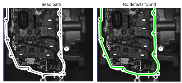
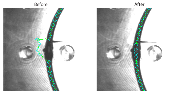
Use a Bead Inspect tool to examine a uniform path of any length and direction. A trained Bead Inspect tool finds defects in images where a bead suffers gaps, over-filling, or other flaws. You train a Bead Inspect Tool with the expected location and appearance of a bead path and then use the trained tool to locate defects in runtime images. For example, the following figure shows a Bead Inspect tool used to examine the path of a glue bead:
In images where no defects exist, your application can highlight the found bead path in green:
To work with a Bead Inspect tool in your vision application, VisionPro offers the CogBeadInspectTool programming interface and the Bead Inspect Edit Control graphical user interface in the QuickBuild utility.
Adding a Bead Inspect tool to your vision application requires the following steps:
- Acquire a training image showing a good example of the bead you want to analyze in runtime images.
- Allow the tool to find the approximate location, shape and width of the path.
- Manually refine the reported position of the bead path so that it accurately matches the actual path in the training image.
- Train the tool with the accurate location of the bead path you want it to examine.
- Choose a set of runtime parameters that limit how much variation the bead path can display in successive images and still allow the tool to return a passing result.
See the following sections for more information:
Before you can train a Bead Inspect tool with the features of the particular bead path you want to inspect in your runtime images, the tool must be able to accurately find the path in a sample image.
Perform the following steps to find the bead path:
- Provide the Bead Inspect tool with a good image of the bead path and pass this image to the Train Image property of the tool.
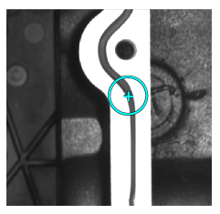
Use the Start Circle property on your Train Image to define the bead of interest and a starting location for finding the bead path.
Locate and define the Start Circle so it contains only the bead path surrounded by features that differentiate it from background pixels:
Allow the tool to determine the best settings for the following parameters automatically, or set these parameters manually:
- Bead Width: The expected width of the bead to search for
- Contrast Threshold: A contrast threshold used to detect the bead edges
- Dark Bead: Indicates the bead path consists of pixels darker than the background pixels
- Use the Bead Inspect tool Find method to have the tool detect the features in the image corresponding to the bead path.
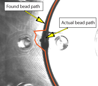
The Bead Inspect tool analyzes the sample image with different search parameters and attempts to generate one or more coarse paths that accurately track the bead path in your sample image. Depending on the features in your image, some coarse paths might accurately reflect the bead path while others will not:
Continue to train a Bead Inspect tool for use by choosing the best coarse path for your sample image.
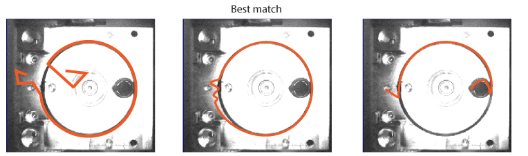
By default a Bead Inspect tool generates a collection of five coarse bead paths after you use the Find method to find the bead path in your sample image.
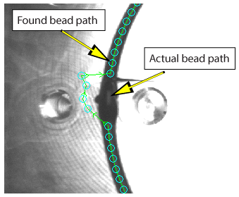
View the collection to determine which coarse path best matches the bead path in your sample image. Be aware that even the best match for a coarse path might not match the location of the bead path in all areas:
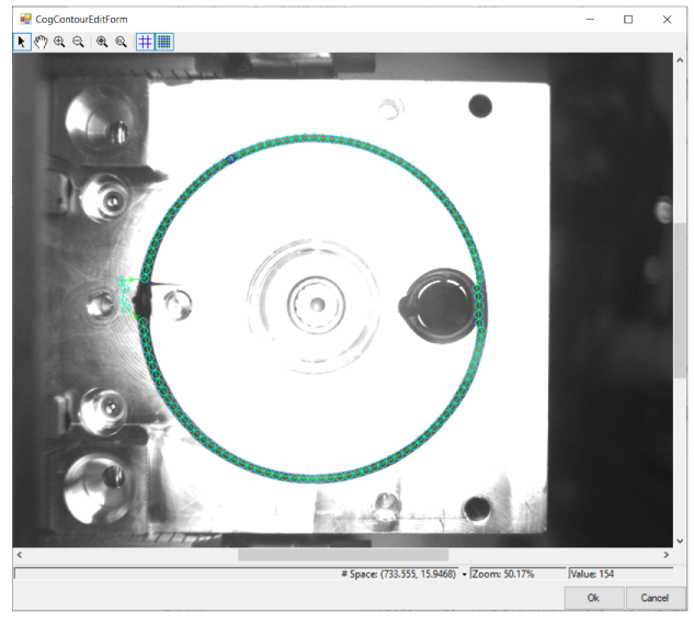
The Bead Inspect tool allows you to modify a coarse bead path so that it closely matches the actual path in your sample image. Use the graphical user interface the tool supports to change a coarse bead path:
The interface uses points and line segments to represent the coarse path:
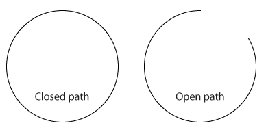
The coarse path can be open or closed depending on your sample image, which impacts how the path can be edited:
Click on points and line segments to modify the coarse path to follow the actual bead path:
- Click and drag individual points to better locations.
- Right-click on line segments when you want to insert a new point at the cursor location.
- Right-click on existing points to delete them as necessary. You cannot delete the first and last point on an open contour path.
- Select Open Closed Contour to delete the line segment between two points on a closed contour path.
- Select Delete Points Before or Delete Points After to delete all points before or after the selected point on an open contour path.
When you are done the coarse path should follow the actual bead path as much as possible:
Save the changes you make. With a coarse path that matches the actual bead path in your sample image you can now train the tool to find the path in all your runtime images.
Once you have a coarse bead path that closely matches the actual bead path in your Train Image, you can Train this pattern for the tool.
The Bead Inspect tool supports a set of run parameters that allow the bead path in your runtime images to vary in appearance and still allow the tool to return a passing result.
For example, set the Contrast Threshold to set the minimum contrast required for detecting the edges of the bead. Any runtime image where bead path pixels fall below this threshold will cause the tool to return one or more defects.
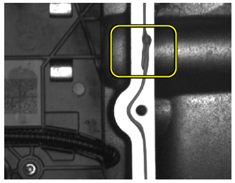
The Bead Inspect tool allows you to ignore or modify imprecise areas of a bead path which could otherwise result in false defects. For example, the following figure highlights a section of a bead path that your application can safely ignore in run-time images:
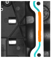
The following figure shows the training image where the corresponding range of points has been masked out of consideration:
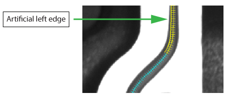
In addition to selecting segments of the bead path the tool will completely ignore, you can select segments where the Bead Inspect tool will create an artificial right or left edge in images where these limitations exist and you need the application to avoid generating defects about missing edges. The following figure indicates points in the training image that will compensate for missing left edges:
Use the Bead Inspect Edit Control or the MaskList property to generate a list of points on the bead path that should be ignored in run-time images when searching for defects.
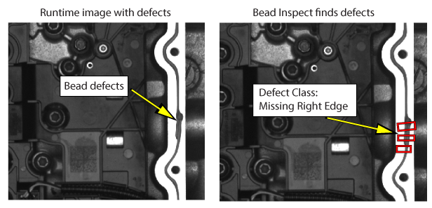
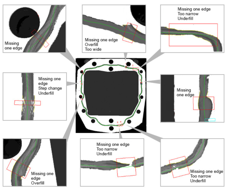
Bead path defects generally fall into one of the following categories:
- No path can be found or the path contains gaps.
- The path is too narrow or too wide compared to the training image.
- The Bead Inspect tool cannot accurately determine the left edge or right edge of the path for a given location.
The following figure illustrates the type of defects a Bead Inspect tool can detect:
The VisionPro QuickBuild utility supports a Bead Inspect edit control with a user interface for configuring the tool:
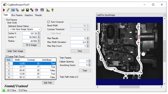
The edit control allows you to create a Train Image, choose and modify a coarse bead path and test the runtime parameters on sample images.
See the topic Bead Inspect Edit Control for details on the Bead Inspect edit control.