The Factory Floor Protocols supported by VisionPro allow you to create an application that can communicate with a compatible Programmable Logic Controller (PLC) across an industrial network. VisionPro supports the following protocols:
- PROFINET (Siemens PLCs)
- EtherNet/IP (Rockwell PLCs)
- SLMP (Mitsubishi PLCs)
The Cognex implementation of the factory floor protocols is based on the Cognex Network Data Model (NDM), a protocol-independent abstraction that allows your application to work with any supported protocol without modification.
The NDM allows both the vision application and the corresponding PLC application (running on the PLC) to interact with a familiar, platform-appropriate interface.
On the PLC, the NDM is represented as a signal table. The signal table defines a collection of status and control signals that the PLC and the vision application use to communicate. Signals are represented as named sections consisting of one or more bits of memory on the PLC. The overall signal table is represented as a pair of sub-tables that define the overall layout of the signal bits:
- An status table, that contains the signals and memory that are set by the vision application and read by the PLC application.
- An control table, that contains the signals and memory that are set by the PLC application and read by the vision application
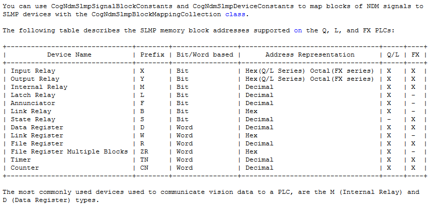
Note: The SLMP connection uses a modified version of the NDM signal table layout. For Mitsubishi customers, bit-typed data is stored in bit registers in the PLC, and word-type data is stored in word registers in the PLC. Due to this implementation, bit data is never grouped with word data in a data block, which allows these data items to be addressed separately in the PLC.
The PLC implementation also includes blocks of memory that can be used for sending configuration information to the vision application (such as the name of a job to load ) and for sending results data to the PLC (such as a decoded string or a collection of part measurements).
Within the vision application, the NDM is represented as a collection of notification functions and events. Your application invokes the notification functions to raise or lower the state of signal in the signal table. Your application is notified of signal state changes by writing handlers for the NDM events.
Note: The NDM imposes a collection of constraints on the virtual signals. The state of a signal may be changeable or not changeable, from both the PC application and the PLC application, depending on the value of other signals and on the internal state of the NDM.
The following figure provides an overview of how the NDM works, and how it supports communication between your vision application and your PLC.
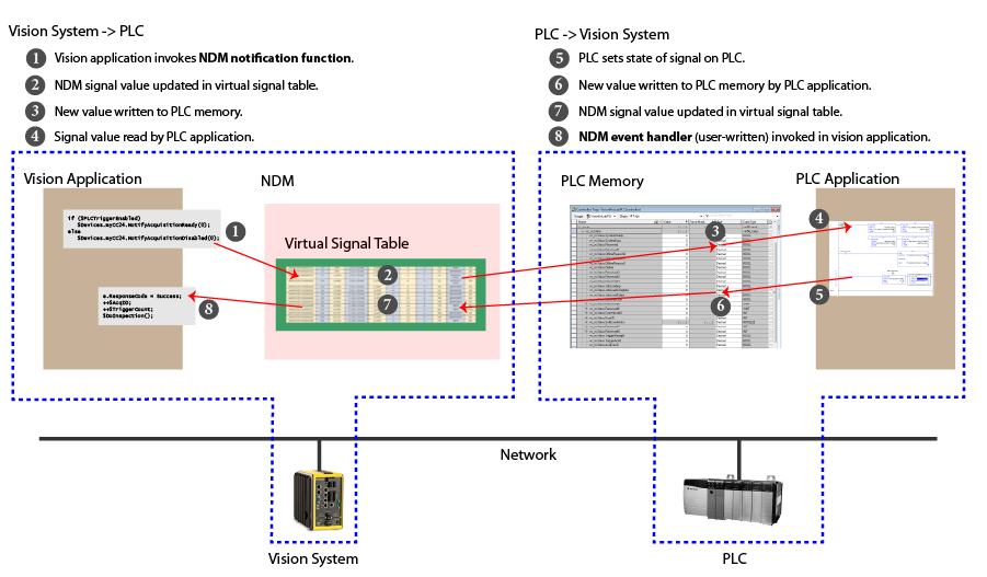
The sequence of events shown in the preceding figure is simplified; in practice, communication tasks are implemented with a series of signal changes.
The NDM lets you:
Invoke image acquisition and inspection under the control of the PLC application. This is typically done for slow-speed application where the PLC is managing the line motion.
The basic signal flow is:
- Vision Application invokes NotifyAcquisitionReady on the selected camera.
- PLC sets TriggerCamera for the selected engine.
- Vision Application TriggerAcquisition() event handler is invoked.
- Vision Application invokes NotifyInspectionComplete(), optionally supplying inspection result data.
Update a PLC with results and status information from a vision application running on your PC.
The basic signal flow is:
- Vision Application is triggered by an external trigger.
- Vision Application invokes NotifyInspectionComplete(), optionally supplying inspection result data.
- PLC processes results.
Note: The PLC can set the Results Buffer Enable signal true to enable buffering of up to 16 results within the NDM.
Change the configuration of a running vision application on your PC from a PLC.
The NDM provides two methods for modifying the configuration:
- Job load signal which lets you specify an ID value to load a job or configuration file.
- A soft event signal, which allows you to invoke one of 31 predefined functions within your vision application.
For the EtherNet/IP and PROFINET protocols, the virtual signal table implemented by the NDM is divided into a status table, which contains signals that are modified by the vision applicaiton, and a control table, which contains signals that are modified by the PLC. The vision application modifies signals in the status signal table by invoking NDM notification functions and it is notified of changes to signals in the control signal table when NDM events are invoked. The PLC simply reads and writes the memory locations that correspond to the signal values in the two tables.
For the SLMP protocol, the defined data blocks allow you to control where the vision system is reading and writing data to and from the Automation Controller. For easier application setup, the various control and status bits required for command functionality are grouped into contiguous blocks, which can be processed together. When setting up the interaction between the vision system and the Automation Controller, you will need to choose the starting address and device type for each block of data.
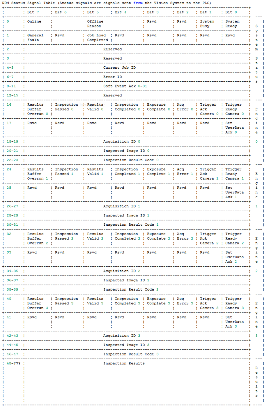
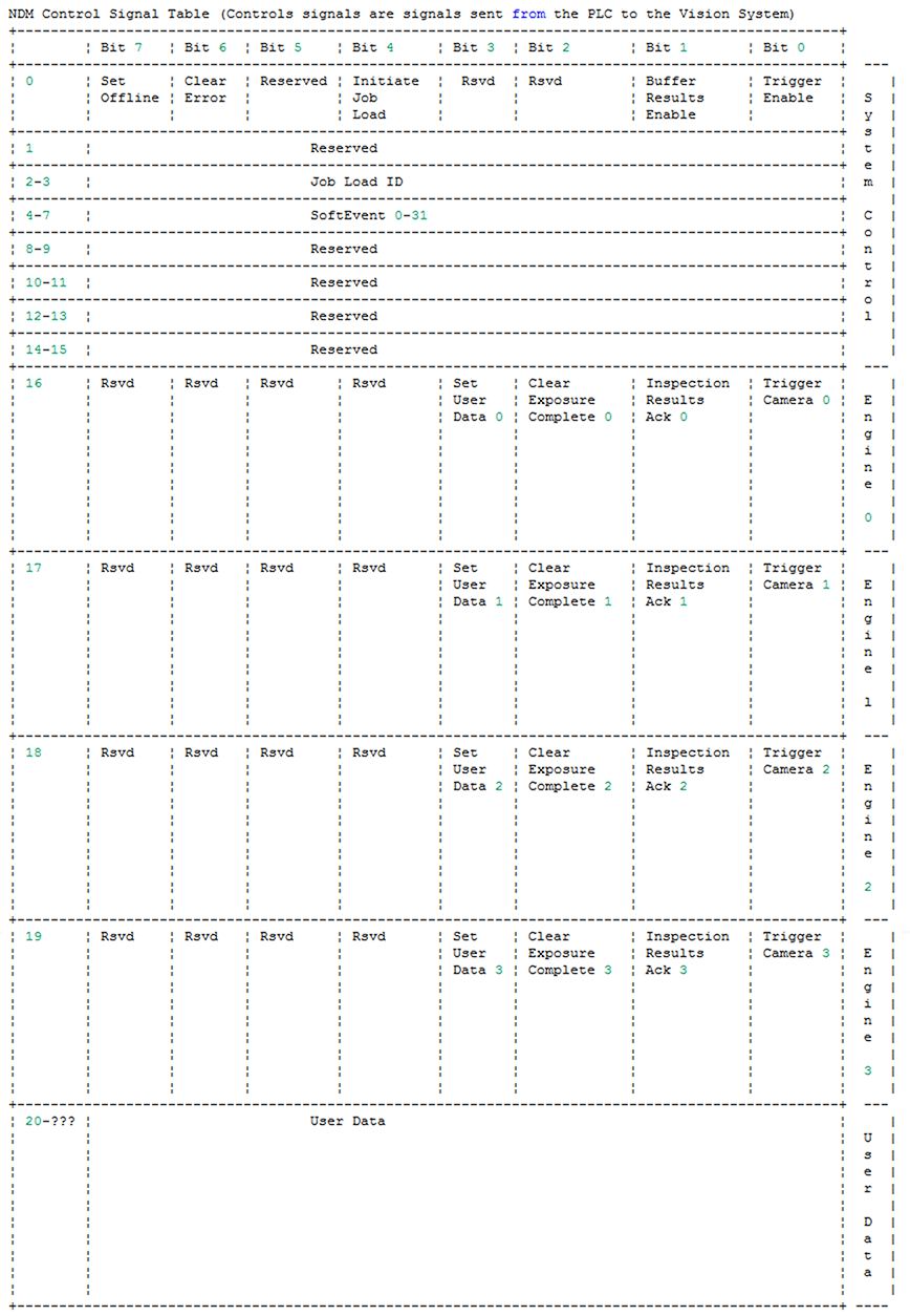
The status and control tables are further partitioned into a system region, an engine section, and a data section.
- The system region contains signals that are related to the overall state of the NDM, such as online and offline state.
- The engine region contains four identical blocks of memory that correspond to the four cameras and inspection jobs that can be run concurrently on the vision system.
- The data section contains data written from the vision system to the PLC (results inspection results) and from the PLC to the vision system (user data).
The following signal table maps describe the overall organization of both the status and control signal tables for EtherNet/IP, PROFINET and SLMP.
Note: The specific memory layout on your PLC depends on the protocol and PLC type.
- For EtherNet/IP PLCs, the signal table layout corresponds exactly to the memory layout on the PLC.
- For PROFINET PLCs, the memory layout is described in the supplied GSD file.
- For Mitsubishi PLCs, the signal table groups the NDM signals into four blocks. Each block contains only single bit signals, or signals that take up an entire word.
The following table shows the layout of the status signal table for EtherNet/IP and PROFINET:
The following table shows the layout of the control signal table for EtherNet/IP and PROFINET:
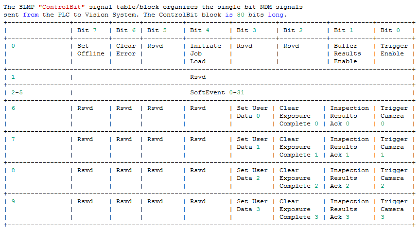
The following table shows the layout of the SLMP ControlBit block:
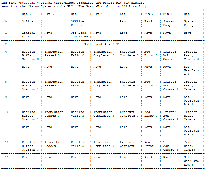
The following table shows the layout of the SLMP StatusBit block:
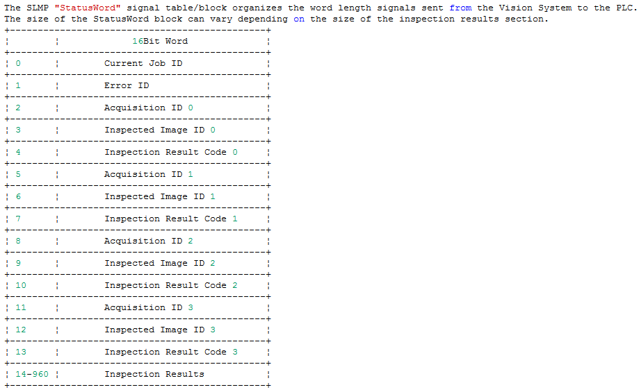
The following table shows the layout of the SLMP StatusWord block:
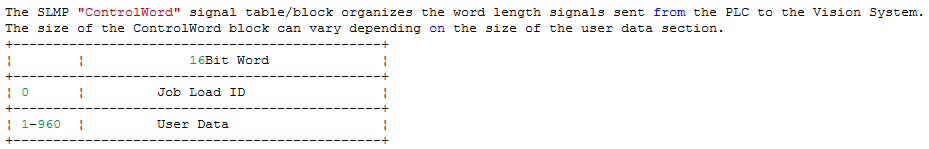
The following table shows the layout of the SLMP ControlWord block:
The following table shows the layout of the SLMP memory block addresses: