This topic contains the following sections.
- The Caliper Tool
- Fitting Tools
- Ignoring Points
- How The Shape Finding Tools Work
- Finding Lines
- Caliper Placement and the Expected Line Segment
- Specifying Search Direction
- Finding the Line
- Finding Circles
- Caliper Placement and the Expected Circle
- Finding Corners
- Caliper Placement and the Expected Line Segments
- Finding Ellipses
- Caliper Placement and the Expected Ellipse
The following Shape Finding tools are available:
- The Circle Finding tool, finding circles
- The Line Finding tool, finding lines
- The Corner Finding tool, finding corners
- The Ellipse Finding tool, finding ellipses
The Shape Finding tools provide an easy to use interface for finding circles, lines, corners, and ellipses. You can of course, write your own shape finder by calling the Caliper tool and Fitting tools directly from your application.
The Shape Finding tools find edge points on a shape by repeatedly calling the Caliper tool. An important part of using the Shape Finding tools is selecting the right number of calipers. Calipers should be chosen so that the shape edge you wish to find is the only edge inside the caliper. If the caliper input region contains multiple edges, then you should make sure that the caliper is configured to report the desired edge first.
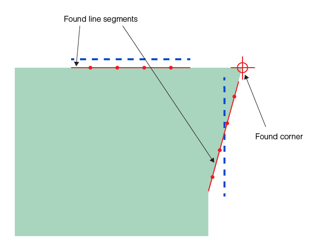
When you run the Shape Finding tools, you provide the Caliper tool run-time parameters it will use. For this reason, you must be familiar with the Caliper tool and how to use it in your application. For example, you would run the Caliper tool in single-edge mode to find the left-hand example line in Figure 1, while the right-hand example line has two edges and requires that you either run the Caliper tool in edge-pair mode, or that you specify the polarity of the expected edge explicitly. Set the Caliper tool run-time parameters so that the tool finds a result point that the Shape Finding tools can use as an input to a Fitting tool.
Figure 1. Caliper examples
The Fitting tools include the Line Fitting tool, the Circle Fitting tool, and the Ellipse Fitting tool. Once the Shape Finding tools have found the edge points using calls to the Caliper tool, it passes these points to the proper fitting tool to fit the shape. An important part of this procedure is that fitting tools require a minimum number of points. The Line Fitting tool requires at least two points, the Circle Fitting tool requires at least three points, and the Ellipse Fitting tool requires at least five points. For better results, always provide more than the minimum number of required points.
Note that there is no corner fitting tool, the corner is determined by two fitted lines. A hypothetical corner fitting tool would have to determine the corner based on points only, which do not define the corner unequivocally because the orientation of the corner can be arbitrary.
Fitting tools have a run-time parameter that specifies a number of input points it can ignore to make a better fit. This allows the tool to ignore outlier points and just use the best-fit points to fit the shape. When you specify the number of calipers to use in your application, allow extra calipers and then specify a number of points that can be ignored by the fitting tool. In most cases, this will produce more accurate results.
In some cases a caliper may fail and not produce a point to be carried forward to the Fitting tool. In this case, the Fitting tool will have fewer points to work with than your design calls for. Also, if you have specified that the Fitting tool can ignore some points, caliper failures can leave the Fitting tool with fewer points than needed for a successful fit. To protect against this condition, the Shape Finding tools have a feature you can enable that will automatically decrement the Finder tool ignore count for every caliper that fails. When you use an ignore count with your Fitting tool, we recommend you also enable this auto-decrement feature.
The Shape Finding tools work by using the Caliper tool to locate shape edge points along an expected shape that you supply. This section describes how the Line Finding, Circle Finding, Corner Finding, and Ellipse Finding tools work.
This section describes how the Shape Finding tools find a line in an image.
To use this tool, you must know the approximate location of the line segment you wish to find in the image. You specify the number of calipers to use and the tool then distributes the calipers along the expected line segment. The expected line you specify should be close to the actual line you wish to find in the image.
You also specify the geometry and run-time parameters that are used by all the calipers. The Shape Finding tool spaces the calipers evenly along the expected line segment you supply.
The line you define should be close to the actual image line you wish to find. If you plan to run the tool on many images and you expect some variations from one image to the next, make your expected line sufficiently shorter than the actual line so that the calipers will always find a line edge.
The Line Finder tool divides the expected line into equal segments, one per caliper, according to the number of calipers you specify. It then centers a caliper on each line segment. An example showing four calipers is shown in Figure 2.
Figure 2. Specifying the expected line
By default, the caliper search direction is +90˚, measured from the expected line. To avoid including extraneous edges or other image features inside a caliper region, you can adjust the skew of the caliper by specifying a different value for the search direction, as shown in Figure 3.
Figure 3. Skewed calipers
Once the calipers are placed, the tool runs each caliper to find an edge point. By default, the tool assumes that the line is the only edge point inside the caliper. If there are multiple edges inside the input region, you must specify caliper parameters that will return the desired edge first.
Figure 4 is an example of an expected line with four calipers. The example purposely uses an expected line angle somewhat different from the actual line angle to illustrate the angle tolerance you have to work with. The critical factors include making sure the image line edge falls inside each caliper, and ensuring no other features inside the calipers might be mistaken for a line edge.
Figure 4. Expected line with four calipers
Figure 5 shows the edge points found after the tool runs the calipers.
Figure 5. Found line edge points
The found edge points are then applied to the Line Fitting tool which fits an infinite length line to the points. The fitted line is shown in Figure 6.
Figure 6. Found line
The infinite length line shown in Figure 6 is shortened to a line segment using a projection of the expected line. The projection is performed by determining the point on the fitted line that is closest to the midpoint of the expected line, then using that as the midpoint of a segment of the expected length along the fitted line. Figure 7 shows how the expected line length is used to establish the found line segment.
Figure 7. Returned line segment
This section describes how the Shape Finder tool finds a circle in an image.
To use this tool, you must know the approximate location of the circle you wish to find in the image. You supply this information to the tool as an expected circular arc. In addition, you specify the number of calipers to use to generate edge points, the geometry used for all of the calipers, and the angle range across which the calipers are to be placed. The tool evenly spaces the calipers along the angle range of the circle.
Figure 8 shows an example of an expected circle and four calipers. The angle range specified for this example starts at -150˚ and extends for 120˚.
Figure 8. Expected circular arc with four calipers

Note that although the expected circle is not exactly coincident with the image circle, it is close enough so that the calipers all see an image circle edge. This is the important consideration.
In addition to specifying the expected circle and arc segment, you also provide the geometry used for each of the caliper regions. Figure 9 shows how you specify the caliper geometry.
Figure 9. Caliper geometry for finding circles

Unlike the Line Finding tool, you cannot specify a skew angle for the calipers. You can specify that the search direction be toward or away from the center of the expected circle.
After placing the calipers, the tool calls the Caliper tool once for each caliper, using the same run-time parameters for each call. Figure 10 show the edge points found by the Caliper tool.
Figure 10. Found circle edge points
The found circle edges are applied to the Circle Fitting tool which fits a circle to the points. Figure 11 shows the final fitted circle which is included in the tool result.
Figure 11. Found circle
The circle shown in Figure 11 is shortened to an arc segment by applying the angle start and angle span you specified for the expected arc segment. Figure 7 shows how the expected angle start and angle span are used to construct the returned arc segment.
Figure 12. Returned arc segment
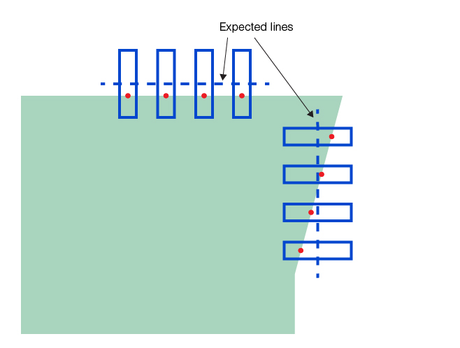
This section describes how the Shape Finding tools find a corner in an image.
A corner is defined by the intersection of two line segments. To use this tool, you must know the approximate location of the line segments that define the corner you wish to find in the image. You specify the number of calipers to use, the same number for both line segments, and the tool then distributes the calipers along the expected line segments. The expected lines you specify should be close to the actual lines you wish to find in the image.
You also specify the geometry and run-time parameters that are used by all the calipers of both line segments. The Shape Finding tool spaces the calipers evenly along both of the expected line segments you supply. You can use only one of the two line segments to specify these parameters. You can specify only the position of the other line segment.
The same parameter setting considerations apply to the line segments of the Corner Finding tool as to that of the Line Finding tool.
Figure 13 shows the edge points found after the tool runs the calipers.
Figure 13. Expected lines and found line edge points
The found edge points are then applied to the Line Fitting tool which fits two infinite length lines to the two set of points. The fitted lines and the corner they define are shown in Figure 14.
Figure 14. Found lines

The infinite length lines shown in Figure 14 are shortened to line segments using projections of the expected lines. The projections of the lines are performed the same way as in the case of the Line Finding tool. Figure 15 shows the found line segments and the corner.
Figure 15. Returned line segments and corner
This section describes how the Shape Finding tools find an ellipse in an image.
To use this tool, you must know the approximate location of the ellipse you wish to find in the image. You supply this information to the tool as an expected elliptical arc. You specify the center, radii, and rotation of the expected elliptical arc. In addition, you specify the number of calipers to use to generate edge points, the geometry used for all of the calipers, and the angle range across which the calipers are to be placed. The tool evenly spaces the calipers along the angle range of the ellipse.
Hereinafter, ellipse finding with an expected elliptical arc of zero rotation is shown.
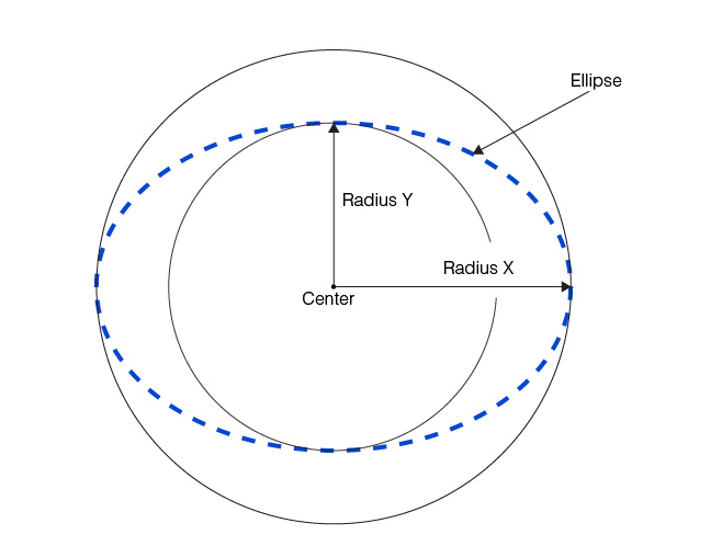
The following figure shows the Radius X and Radius Y properties of an ellipse.
Figure 16. Ellipse radii
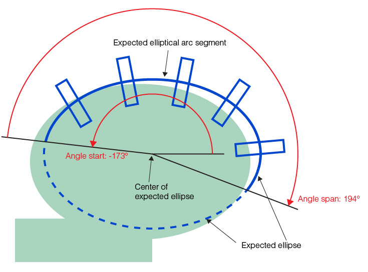
The following figure shows an example of an expected ellipse and five calipers. The angle range specified for this example starts at -173˚ and extends for 194˚.
Figure 17. Expected elliptical arc with five calipers
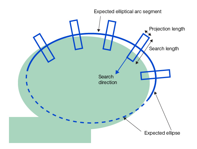
In addition to specifying the expected ellipse and elliptical arc segment, you also provide the geometry used for each of the caliper regions. The following figure shows how you specify the caliper geometry.
Figure 18. Caliper geometry for finding ellipses
After placing the calipers, the tool calls the Caliper tool once for each caliper, using the same run-time parameters for each call. The following figure shows the edge points found by the Caliper tool.
Figure 19. Found ellipse edge points
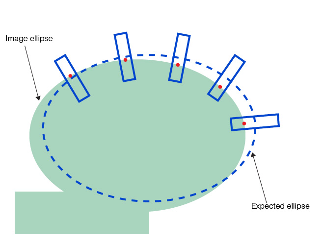
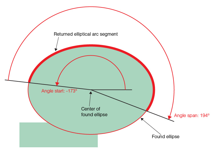
Figure 20. Found ellipse
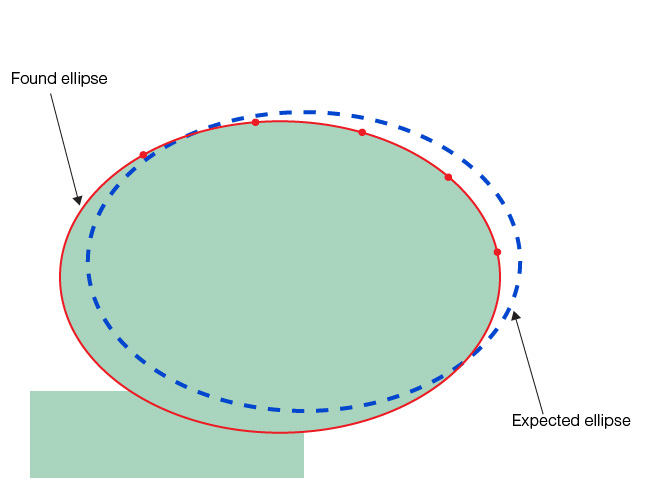
Figure 21. Returned elliptical arc segment