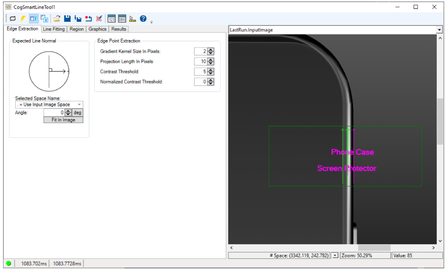
The SmartLine edit control provides a graphical user interface to the SmartLineTool, which you can use in your vision application to locate line features by training the tool with sample images. See the topic Finding Lines with a SmartLine Tool for more information.
The following figure shows an example SmartLine edit control:
A SmartLine tool can be easier to configure than a LineMax tool for some applications.
See the following sections for more information:

The following table describes the function of each button in the button bar:
| Button | Description | Function |
 | Run | Examine the Current.InputImage and search for line features fitting the trained parameters. |
 | Local image display | Open or close the local image display window. A Segment tool supports the following image buffers:
The edit control does not open the local image display by default, unless you choose the Graphics tab. |
 | Floating image display | Open one or more floating image windows, which support the same image buffers as the local image display window. |
 | Open | Open a VisionPro persistence (.vpp) file that contains a set of saved properties for this vision tool object type. VisionPro reports an error if you try to open a .vpp file for another object type. |
 | Save | Save the current properties of the vision tool to a VisionPro persistence (.vpp) file. The edit control allows you to choose between saving the vision tool with or without its image buffers and tool results. |
 | Save As | Save the current properties of the vision tool to a new VisionPro persistence (.vpp) file. |
 | Reset | Reset the vision tool to its default state. The tool gives you a choice between resetting to the default-constructed state, which is appropriate when you are using it in a Visual Studio.NET application, or its template-initialized state, which is appropriate for QuickBuild applications. |
 | Open Image Mask | Open the Image Mask Editor |
 | Show Floating Results | Open a separate results window with the same contents as seen in the Results tab. |
 | Show ToolTips | Enable or disable the display of tooltips for individual items in the edit control. |
 | Help | Open this VisionPro online help file. |
Use the Edge Extraction tab to configure how a SmartLine tool detects candidate edge points:
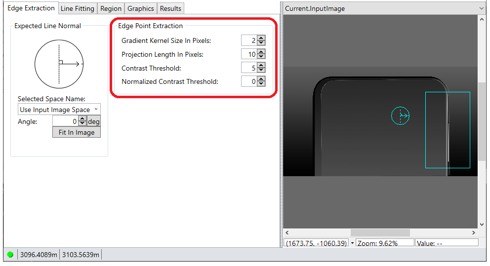
The Edge Extraction tab supports two sets of parameters:
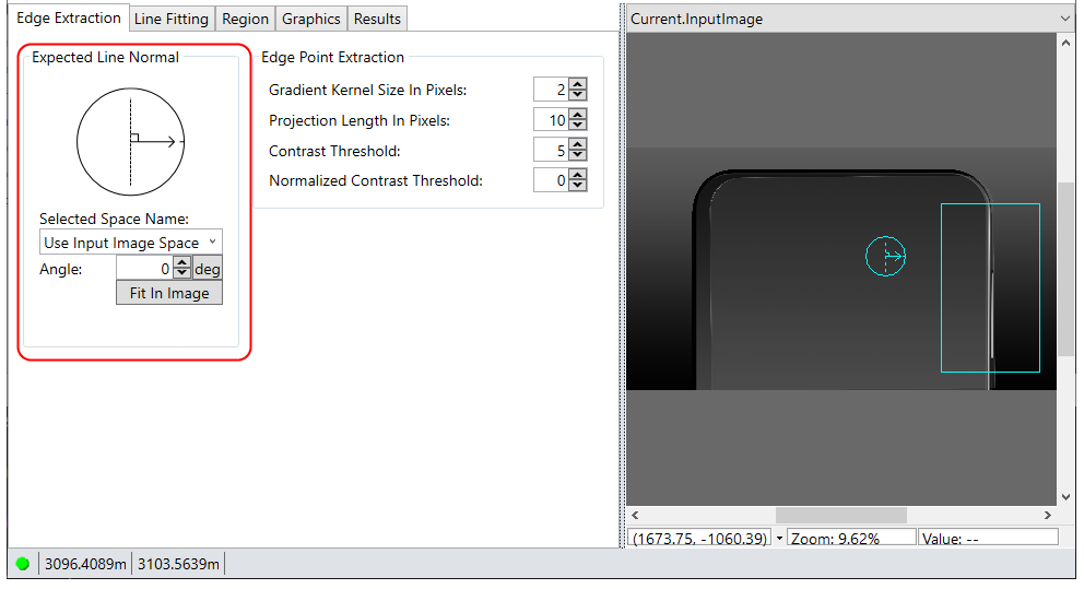
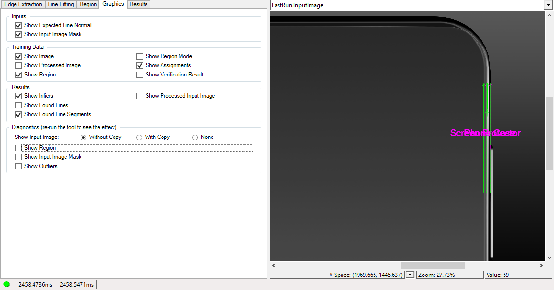
The edit control places an interactive graphic over the Current.InputImage buffer to assist you in specifying the orientation of the line you want to find:
Be aware this is not the search region for locating line segments, which you can configure on the Region tab.
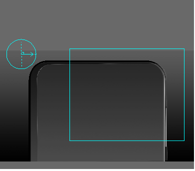
Click on the graphic to enable sizing and rotation handles and use it to specify the expected orientation of the line segments you want to locate. See the following examples for how to use the graphic:
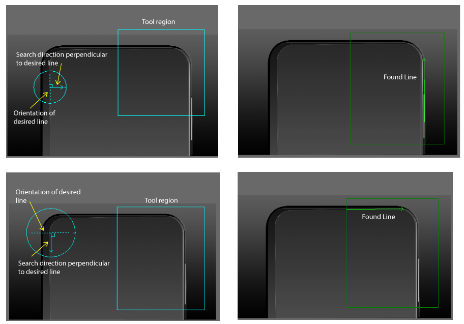
As you use the graphic be aware of the following:
The graphic does not designate a specific region to search for candidate edge points.
By default the tool searches a RectangleAffine for candidate edge points in the direction you specify. Use the Region tab to specify a limited region to search for edge points as your vision application requires. Use a Fixture Tool to compensate for how the search region must be reoriented in successive run-time images.
- The graphic does not specify the polarity of the edge points to search for.
- If you specify a polarity that is not available along the search direction, the tool will not find candidate edge points.
The following parameters determine how a SmartLine tool detects edge points in the input image:
| Parameter | Description |
Gradient Kernel Size in Pixels | The tool uses this value to analyze the run-time image and generate a set of gradient vectors representing edge information. Use a small value when the features of interest in your images display sharp edges, where the transition between light and dark pixels occurs over a short distance. Increase this value for smoother edges in your images. |
Projection Length in Pixels | Determines the number of areas used for gradient field projection:
In general, use a value at least as large as your setting for Gradient Kernel Size in Pixels, but it can be set higher if the tool continues to locate the desired edge points. |
Contrast Threshold | Specify the minimum contrast for an edge to be considered a candidate edge for the feature you want to locate. Increase this value to locate edges of stark contrast and ignore edges where the transition between light and dark pixels is not as prominent, or lower this value when the contrast in the edges you want to locate in your images is small. The contrast of an edge is the absolute difference in average pixel values across the edge, in the range 0 through 255. Only edges with contrast greater than the value you specify are considered by the tool. For example, setting this value to 10 rejects edge points with a contrast below 10 pixel values. |
| Normalized Contrast Threshold | Raise the value of this parameter to discard false edge points in bright areas of your image. Be aware that setting it to 1 discards all edge points, making the tool effectively nonfunctional. |
Use the Line Fitting tab to configure how the tool locates lines from candidate edge points:
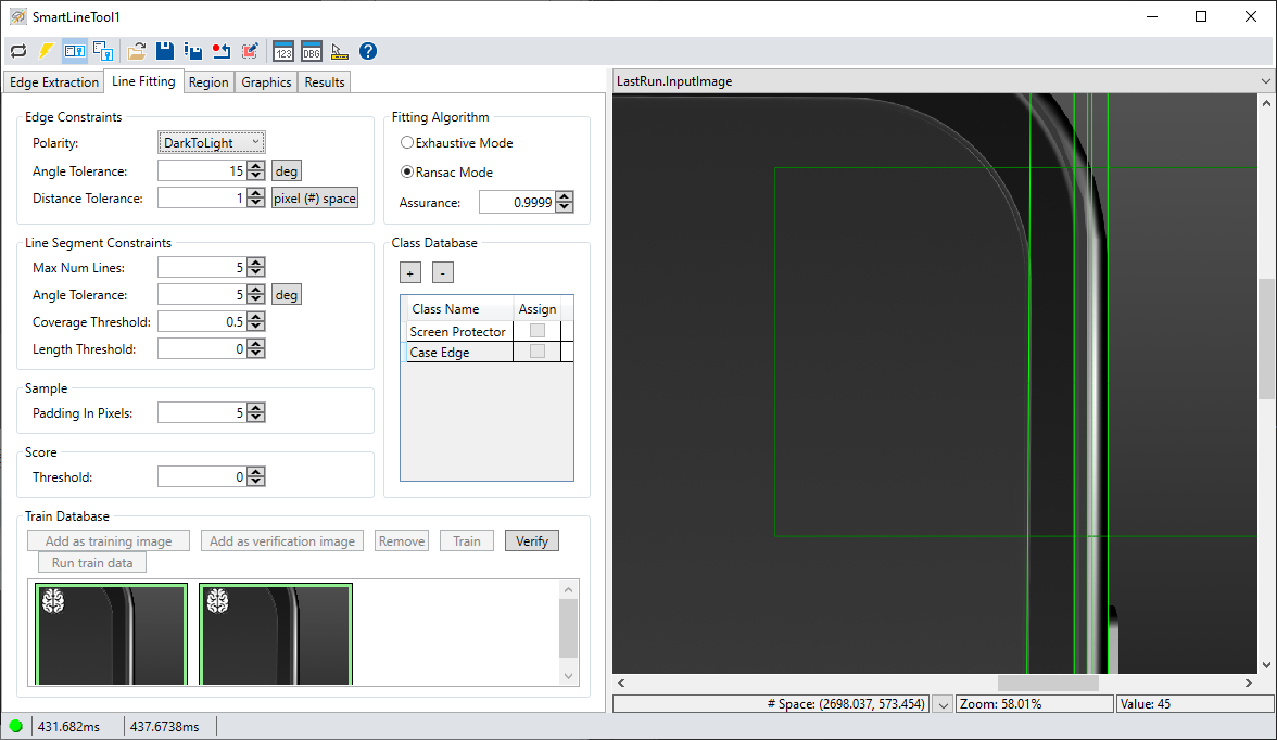
The tab supports the following components:
Specify the following parameters:
| Parameter | Description |
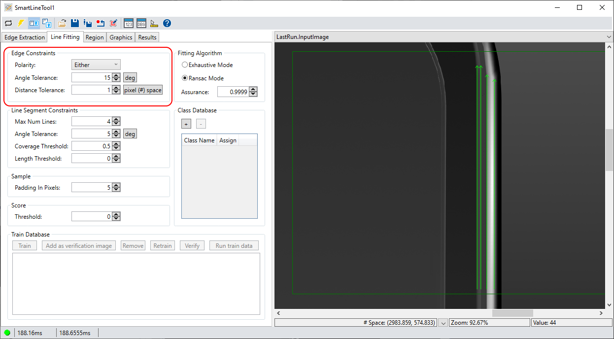
| Polarity | The polarity of the edge points to include in the line. |
| Angle Tolerance | The maximum allowable angle difference between an edge point gradient direction and the normal to the fit line. Increasing this value allows the tool to consider more edge points as inliers while changing the location of the found line segment. |
| Distance Tolerance | The maximum allowable distance between an inlier and a fitted line. As you increase the edge distance tolerance, you allow the tool to consider more edge points as inliers while changing the location of the found line. |

Configure the following constraints:
| Parameter | Description |
Max Num Lines | The maximum number of lines you want the tool to locate. Be aware the edit control supports this parameter only when your VisionPro installation includes the VisionPro.LineMaxMulti license. See the topic VisionPro Security Devices for details on VisionPro security. Set this value to 0 to prevent the tool from returning any line results but still generate a set of outliers for use in your vision application. |
Angle Tolerance | The amount of rotation a found line segment can differ from the expected angle that you specify. A low value forces the tool to locate line segments that are more parallel with the gradient search direction. |
Coverage Threshold | The minimum acceptable ratio of inliers to the maximum possible number of inliers, or the minimum proportion of edge features along the line segment. For example, specifying a value of 0.5 allows the tool to locate a line segment even though edge points were not detected over 50% of the line. Use Coverage Threshold and Length Threshold simultaneously to meet your line fitting requirements. Be aware that specifying a value of 1.0 forces the tool to locate a line segment only when there are no gaps where no inliers were found. |
| Length Threshold | Set the minimum acceptable length of a found line segment. |
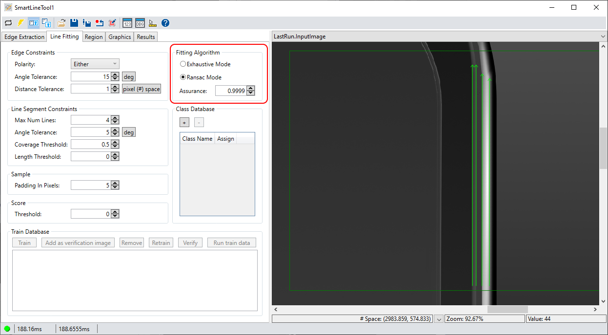
Choose either of the following algorithms for fitting edge points to lines:
| Parameter | Description |
| Exhaustive Mode | All edge point combinations are evaluated for line fitting. |
RANSAC Mode | Random Sample Consensus (RANSAC): An algorithm for robust fitting of edge points in the presence of many edge point candidates. The value for Assurance affects the likelihood that the best edge points will be selected for line fitting. |
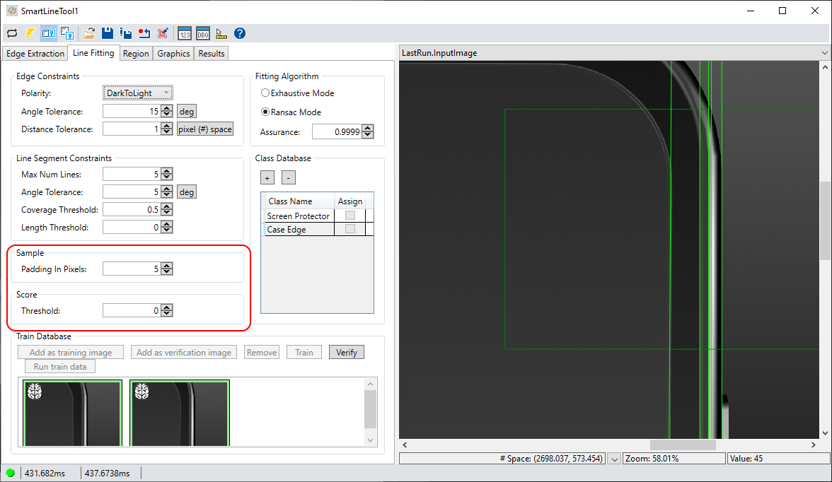
Use the following parameters for finding desired lines in your run-time images:
| Parameter | Description |
Sample - Padding in Pixels | Defines the value of the padding around the training shape in order to provide more pixel information for the segmentation algorithm. Note: Changing the value causes a trained SmartLine tool to become untrained, and the edit control enables the Train button to retrain the tool. If you run the tool without retraining, the edit control displays an error message that the tool is not trained. |
| Score - Threshold | Assigns a minimum score [0 - 1] for a found SmartLine result to be considered as belonging to a particular class defined in the Class Database. |
Use the Class Database and the Train Database to build a database of images the tool uses to find line segments in your run-time images.
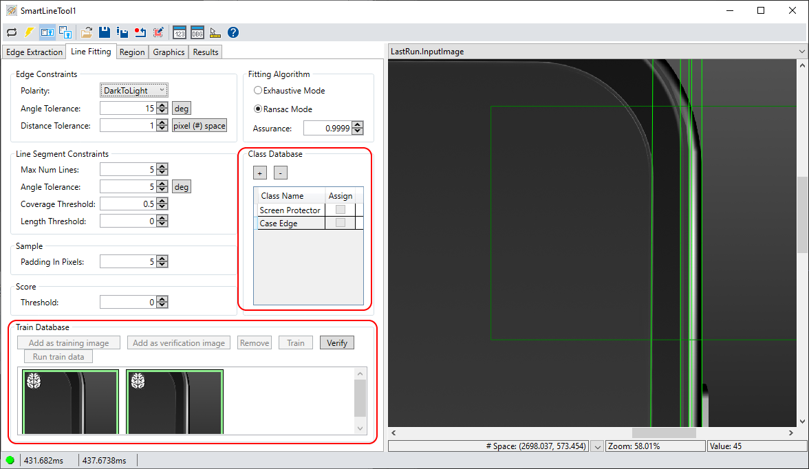
See the topic Finding Lines with a SmartLine Tool for how to train a SmartLine tool to find desired line segments in each image.
Use the Region tab to define the area of the input image where the tool searches for edge points:
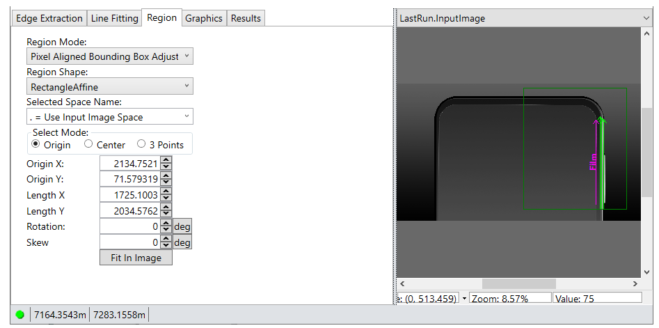
| Parameter | Description |
Region Mode | Defines the bounding box for the region:
|
Region Shape | The shape of the search region.
|
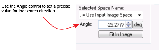
| Selected Space Name | The coordinate space in which the copy region is interpreted. For more information, see the topic Coordinate Space Names. |
| Fit In Image | Centers the search region within Current.InputImage. |
Use the Graphics tab to choose the results graphics the tool displays.
| Operation | Description |
Inputs |
|
Training Data |
|
Results |
|
Diagnostics | Show Input Image: Determine whether or not the input image is recorded as part of the diagnostic record, and whether the image is copied to the record or saved in the record as a reference.
|
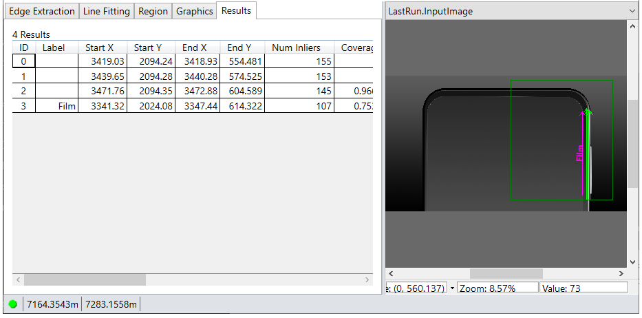
The tool returns the following information about found line segments:
- The Label of any found line segment.
- The (x,y) location, in coordinates of the selected space, for the start and end of the fitted line segment, including its >NormalAngle.
- The number of inliers (Inlier) and the proportion (Inlier) of inliers contributing to this line segment.
- Its polarity (Polarity), intensity (Intensity) and amount of contrast (Contrast)
- A residual RMS fit error (RMSError), relative to the selected space of the input image, from the contributing inliers
- A MaxError reporting the distance of the farthest inlier from the line.
If you set the Max Num Lines parameter to 0 on the Line Fitting tab, the tool returns no line segments but still generates information about edge results with outliers for use in your vision application through the SmartLineTool API.