The Mask Creator tool edit control provides a graphical user interface to the CogMaskCreator tool, which you use to create a runtime mask for any input image. The mask image can be linked to any vision tool that supports image masking and can be fixtured so that it changes orientation to align with the position of desired features in your runtime images.
As you create an image mask you add one or more regions that define areas of Care or Don't Care pixels:
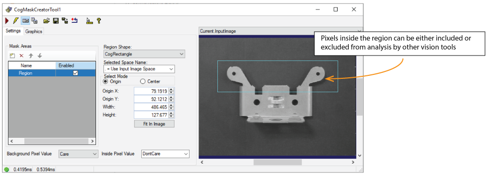
- Position Care regions around features you want to analyze when you attach the mask image to a vision tool later in the application.
- Position Don't Care regions around features you want to exclude from analysis later in the application.
The tool returns a result mask that can be linked to the InputImageMask property of another vision tool such as the LineMax tool.
The following figure shows the Mask Creator edit control:
To include the edit control in your custom vision application it must be in your Visual Studio.NET development environment. See the topic Adding Edit Controls to Visual Studio for more information.
This topic contains the following sections.

The following table describes the function of each button:
| Button | Description | Function |
 | Run | Generate the mask image defined by the regions you create. |
 | Electric mode | Toggle electric mode, where the Mask Creator tool executes automatically when particular configuration parameters change. In electric mode, a lightning bolt appears next to every electric property. |
 | Local image display | Open or close the local image display window. A Mask Creator tool supports the following image buffers:
|
 | Floating image display | Open a floating image window, which supports the same image buffers as the local image display window. |
 | Open | Open a VisionPro persistence (.vpp) file that contains a set of saved properties for this vision tool object type. VisionPro reports an error if you try to open a .vpp file for another object type. |
 | Save | Save the current properties of the vision tool to a VisionPro persistence (.vpp) file. The edit control allows you to choose between saving the vision tool with or without its image buffers and tool results. |
 | Save As | Save the current properties of the vision tool to a new VisionPro persistence (.vpp) file. |
 | Reset | Reset the vision tool to its default state. The tool gives you a choice between resetting to the default-constructed state, which is appropriate when you are using it in a Visual Studio.NET application, and its template-initialized state, which is appropriate for QuickBuild applications. |
 | Show ToolTips | Enable or disable the display of tooltips for individual items in the edit control. |
 | Help | Open this VisionPro online help file. |
Use the Settings tab to create regions of Care and Don't Care pixels. The following figure shows the Settings tab with multiple regions:
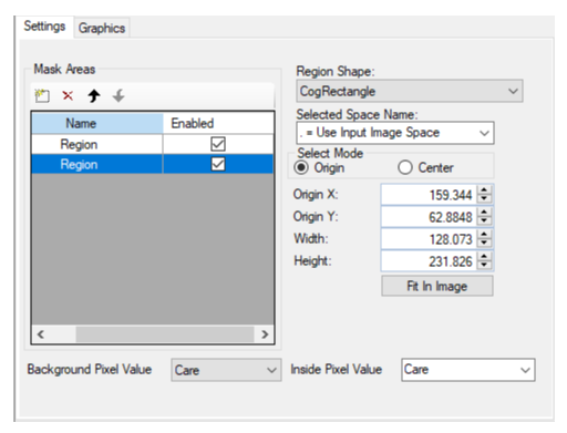
The Settings tab offers the following controls:
| Control | Description |
Choose whether the pixel values of the generated mask image are Care or Don't Care.
| |
Region Grid | Use the grid in the Settings tab to add regions to this mask image: 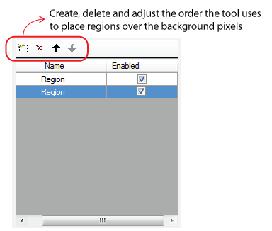 For each region, specify an Inside Pixel Value of Care or Don't Care. Separate regions can be defined as Care or Don't Care depending on your application. Be aware the order of regions as they appear in this grid ultimately determines which image pixels are defined as Care and Don't Care. For example, placing a region of Care pixels over a region of Don't Care pixels makes those image features available for analysis despite the Don't Care region. See the topic Image Masking for more information. |
Select the shape of the region: | |
| Selected Space Name | The default coordinate space for the region. For information, see Coordinate Space Names. |
| Select Mode | Available when Region Shape is CogRectangle or CogRectangleAffine. Selects the set of parameters that define the rectangle. If CogRectangleAffine is chosen, note that the angles of rotation and skew can be specified in degrees or radians, although the underlying tool keeps the measurements in radians. |
| Fit In Image | Centers the region within the mask image and adjust the region's geometric properties so that its default size is based on the image and its Selected Space Name. |
Enable the Show Output Mask checkbox on the Graphics tab to generate a LastRun.OutputMask buffer to contain the mask image as shown:
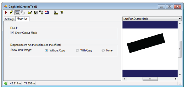
Use the Show Input Image diagnostics to determine whether or not the input image is recorded as part of the diagnostic record, and whether the image is copied to the record or saved in the record as a reference.