Use a Bead Inspect tool to examine the path of a bead and find defects in images where the bead suffers gaps, over-filling, or other flaws. See the topic Using a Bead Inspect Tool for more information on using a Bead Inspect tool.
QuickBuild offers a Bead Inspect tool edit control for training and testing a Bead Inspect tool:
The edit control offers the following features:
- A row of control buttons at the top provide access to the most common operations.
- A set of function tabs allow you to train the path of a bead, provide runtime parameters and view tool results.
- An image display window displays acquired images and graphical results of the Bead Inspect tool.
To include the edit control in your Visual Studio vision application, you must first add it to your .NET development environment. See the topic Adding Edit Controls to Visual Studio for more information.
Use the following features to configure the tool:
Use the Train tab to locate the bead path in a sample image and then train the tool to find it in your runtime images:
You must perform the following steps to train the tool with the path of a bead:
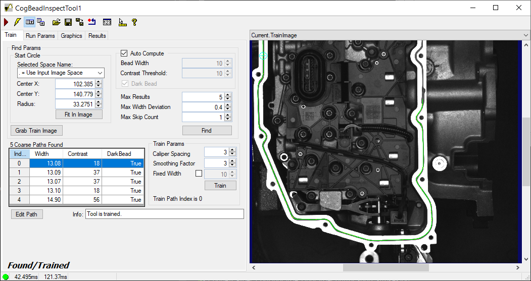
Acquire a good sample image of the bead you want to analyze in runtime images and Run this CogJob to pass the image to the Bead Inspect edit control.
The Current.InputImage displays the sample image.
- Click Grab Train Image to copy the Current.InputImage buffer to the Current.TrainImage buffer.
Switch to the Current.TrainImage buffer and adjust the Start Circle graphic so the center of the circle is as close to the middle of the bead as possible:
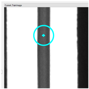
Adjust the Start Circle using the graphics on the Current.TrainImage or use the Start Circle parameters in the tab, which reflect the settings in the Current.TrainImage buffer:
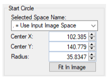
Selected Space Name Coordinate space in which this shape is to be interpreted. Center X X coordinate of the center of the Start Circle Center Y Y coordinate of the center of the Start Circle Radius Radius of the Start Circle Allow the tool to determine the best settings for the following parameters with the Auto Compute checkbox, or set these parameters manually:
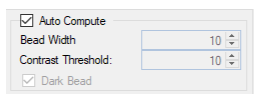
Bead Width The expected width of the bead path to search for, based on the current coordinate system Contrast Threshold The contrast threshold used to detect the edges of the bead Dark Bead Indicates if the bead path is darker than the background pixels Click Find to have the tool detect the features in the image corresponding to the bead path.
The Bead Inspect tool analyzes the sample image with different search parameters and attempts to generate one or more coarse paths that accurately track the bead path in your sample image. Depending on the features in your image, some coarse paths might accurately reflect the bead path while others will not.
The Train tab supports a grid that shows the bead width and contrast of each coarse path and indicates if the found path consists of a dark bead:
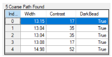
Select any of the coarse paths in the grid to display it in the Current.TrainImage buffer. Before you can train a Bead Inspect tool you must choose which coarse path is the closest to the actual bead path. Based on the coarse paths found, you can adjust the following parameters and perform another Find operation to search the image again for coarse paths:
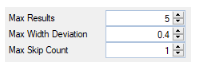
Max Results By default the tool finds a maximum of five coarse bead paths but you can lower that value to have the find operation execute faster. Max Width Deviation The maximum allowable change in the width of the bead path, specified as a fraction of the bead width. Max Skip Count The find algorithm searches along one direction to find the bead path in your sample image. The algorithm can ignore, or jump, over gaps in the expected location of the bead path. The width of the found bead path determines the size of each jump. Set the maximum allowable jumps the algorithm can continue searching along its current direction. After you select which coarse path is closest, the edit control allows you the option to the your chosen path to match the actual bead path even better. Click Edit Path to open a graphical user interface to edit the coarse path. See the section Choosing a Coarse Path for details on how to choose and modify a coarse path before training the tool. Save any changes you make to the desired coarse path.
Click Train once you have a coarse path that matches the actual bead path in your sample image.
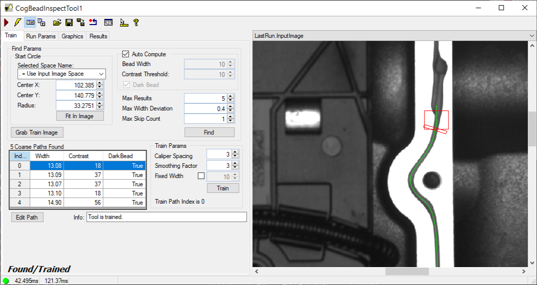
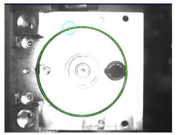
After a successful training the Current.TrainImage buffer highlights the found bead path that the tool will use in your runtime images, as shown in this example:
The Train tab also supports the following parameters that offer additional control over the calipers the tool uses to locate the path of the bead:
Caliper Spacing Set the spacing between caliper center-points along the chosen coarse bead path. Larger values result in fewer calipers along the bead path while a smaller values result in more calipers. Smaller values can increase accuracy at the cost of execution time. Smoothing Factor Set the number of consecutive calipers used to compute the average width values along the trained path. A higher smoothing factor allows the tool an increased tolerance for change in features along the bead path in your acquired images. You might increase this value when variation in the bead path in your images is expected and acceptable. Fixed Width Set a fixed bead width to use when training. The trained pattern will use the value specified here for every point along the bead path rather than the observed bead width in the training image.
This section contains the following subsections.
The Run Params tab supports a set of parameters to locate the bead path in your runtime images and allows you to specify masking and fill edge pixels. See the section Masking and Filling Edges for more information on masking and edge filling.
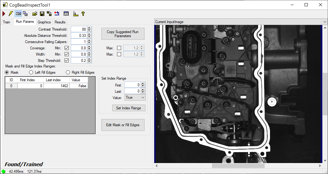
The tool supports the following run parameters:
| Contrast Threshold | Set the absolute minimum difference in average pixel values to indicate the edge of the bead. |
Set the maximum amount an edge position of the bead can deviate in location from the trained bead position, based on a fraction of the average bead width. The default value of 0.5 indicates a bead edge can deviate position as much as half the average width of the bead. Use a low value when the edges of the bead in a runtime image must appear very close to where they were found in the training image, or a higher value when the edges of the bead can drift and the bead can still be considered valid. | |
Set the minimum number of consecutive failing calipers for a defect to be reported. Use a low value to have the tool report small defects in the bead path, or use a higher value if your bead path can contain small defects and still be considered valid. | |
The tool compares the number of bead pixels found in your runtime image to the number of bead pixels found in the training image. Set a minimum and maximum percentage of acceptable coverage, with the tool returning a defect if the bead path in your runtime image is outside of this range. For example, the default value of 0.5 (Coverage Max) allows your runtime image to contain half as many pixels as the bead path in the training image, and the default value of 1.5 (Coverage Min) allow your runtime image to contain 150% more pixels than the bead path in the training image. | |
The tool compares the width of the bead path in your runtime image to the width of the bead path in the training image. Set a minimum and maximum width ratio, with the tool returning a defect if the bead path in your runtime image is outside of this range. | |
Set the maximum relative amount an edge position along the bead path can deviate from neighboring edges, specified as a fraction of the average bead width at that location. A higher value allows the edges of the bead path to deviate with more tolerance. |
When you train a Bead Inspect tool it generates a set of candidate run parameters to find the bead path in your training image. Click Copy Suggested Run Parameters to select which of the suggested run parameters you want to use in the edit control:
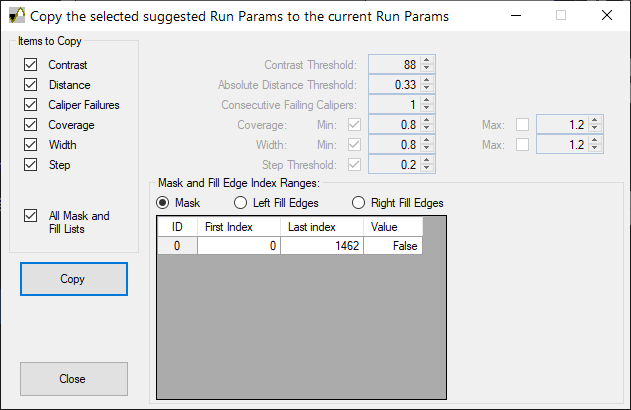
The interface allows you to select some or all the run parameters suggested by the training image, as well as any masking or edge filling index ranges the tool determines you can use to avoid finding any defects in the image you used for training.
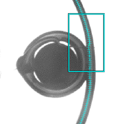
Click Edit Mask or Fill Edges to open an interface that allows you to ignore or modify imprecise areas of a bead path which could otherwise result in false defects:
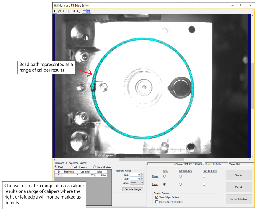
Perform the following steps to use the interface:
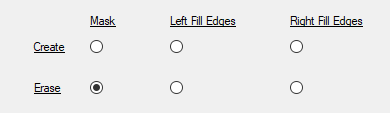
Select Mask, Left Fill Edges, or Right Fill Edges to choose which type of range you want to create:
Zoom in on the image and select caliper results using one of two methods:
- Double-click the caliper results that you want in the masking or edge-filling range.
Use your mouse and draw a rectangle around the caliper results that you want in the masking or edge-filling range:
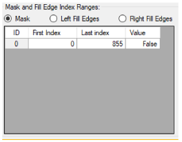
The caliper results in the bead path change appearance depending on the type of range you are creating:
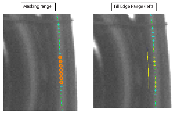
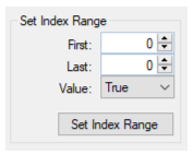
The interface also offers a control that lets you specify the first and last caliper result of the range:
To remove calipers from the range, use the Erase option and select the unwanted calipers (by selecting them directly or drawing a rectangle around them):
- Click Confirm Selection when you are done creating the desired ranges.
- Test your mask or fill ranges on run-time images to see that they generate the expected results.
Use the Graphics tab to enable or disable various graphics over the Current.TrainImage and LastRun.InputImage:
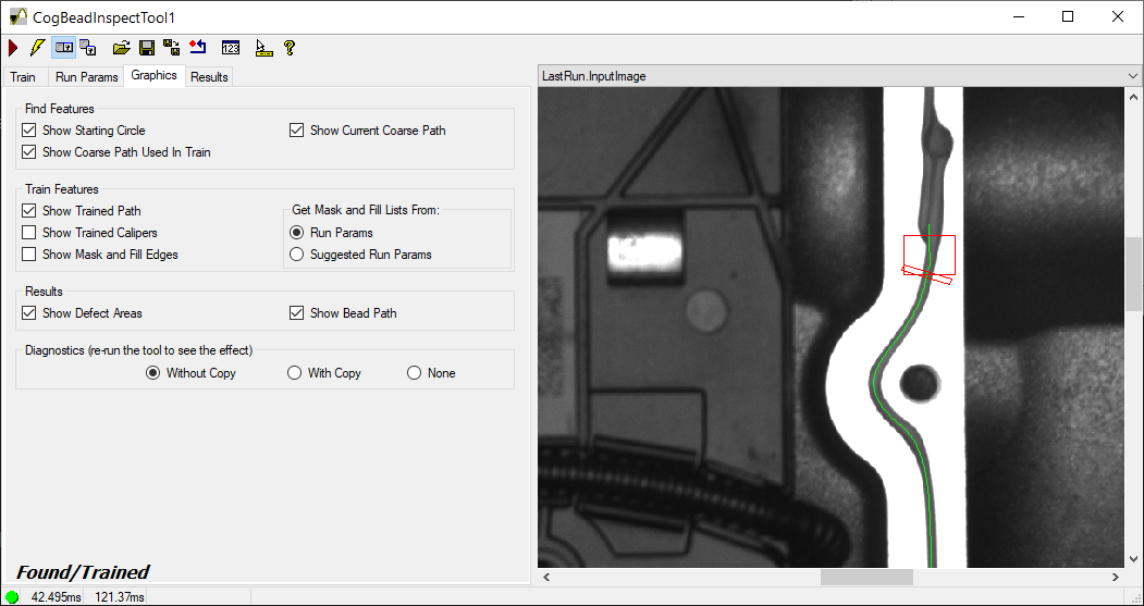
Enable or disable the following graphics over the training image:
| Show Starting Circle | Show the graphic for the Start Circle property the tool uses to find the bead path in the training image. |
| Show Current Coarse Path | Show the coarse path currently selected on the Train tab. |
| Show Coarse Path Used in Train | Show the coarse path used to train the tool with the location of the bead path. |
Enable or disable the following graphics over the training image:
| Show Trained Path | Show the trained path the tool uses to find the bead path in the current image. |
| Show Trained Calipers | Show the calipers used to find the edges of the bead path. |
Show Mask and Fill Edges | Display the caliper results within a mask range or a range of filled edges where the right or left edge will not be marked as defects. The tab allows you to choose from mask and fill lists from the parameters you set on the Run Params tab or the set of candidate run parameters the tool suggests you can use to avoid finding any defects in the image you used for training. |
Enable or disable the following graphics over the current input image:
| Show Defect Areas | Highlight the areas the tool determines are defects. |
| Show Bead Path | Highlight the bead path. |
The Without Copy, With Copy, and None options determine whether or not the input image is recorded as part of the diagnostic record; and whether the image is copied to the record or saved in the record as a reference.
Use the Results tab to view any defects found in the last runtime image:
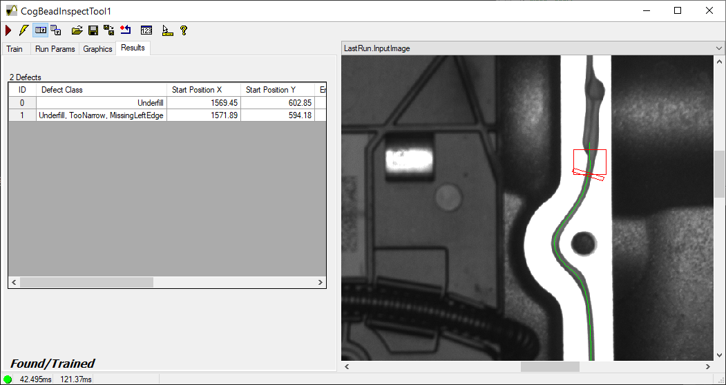
See the section Finding Defects for a list of defects the tool can detect.
The edit control supports a button bar across the top:
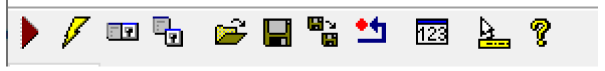
The following table describes the function of each button:
| Button | Description | Function |
 | Run | Run the Bead Inspect tool and examine the current input image for the trained features of a bead path. To run the tool you must have a trained path, an input image and specified run parameters. |
 | Electric mode | Toggle electric mode, where the tool executes automatically when you change the value of certain parameters. In electric mode, a lightning bolt appears next to every electric property. |
 | Local image display | Open or close the local image display window. A Bead Inspect tool supports the following image buffers:
|
 | Floating image display | Open one or more floating image windows, which support the same image buffers as the local image display window. |
 | Open | Open a VisionPro persistence (.vpp) file that contains a set of saved properties for this vision tool object type. VisionPro reports an error if you try to open a .vpp file for another object type. |
 | Save | Save the current properties of the vision tool to a VisionPro persistence (.vpp) file. The edit control allows you to choose between saving the vision tool with or without its image buffers and tool results. |
 | Save As | Save the current properties of the vision tool to a new VisionPro persistence (.vpp) file. |
 | Reset | Reset the tool to its default state. The tool gives you a choice between resetting to the default-constructed state, which is appropriate when you are using it in a Visual Studio .NET application, or its template-initialized state, which is appropriate for QuickBuild applications. |
 | Show Floating Results | Open a separate results window with the same contents as seen in the Results tab. |
 | Show ToolTips | Enable or disable the display of tooltips for individual items in the edit control. |
 | Help | Open this VisionPro online help file. |