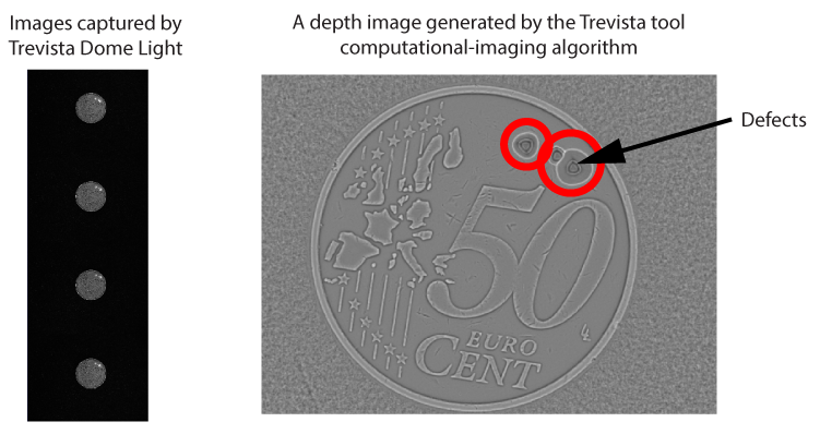
The Trevista tool edit control provides a graphical user interface to the CogTrevistaTool, which accepts an interlaced image from a Trevista CI Dome and uses computational imaging to generate output images to highlight features that raw camera images cannot display. The following figure shows an input image from a Trevista Dome Light and the depth image it generates to highlight surface defects:
See the topic Using a Trevista Tool for an introduction to using a Trevista CI Module. The following figure shows the Trevista tool edit control available in QuickBuild:
See the following sections for more information:
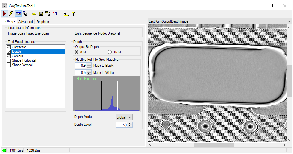
Use the Settings tab to determine which output images you want to generate and set various output image parameters:
The Settings tab offers the following controls:
| Control | Description |
Tool Result Images | Enabling the checkbox for a given type of image enables the production of the named result image, while selecting the row displays the properties specific to that image. See the topic Using a Trevista Tool for descriptions. |
| Output Bit Depth | For the selected image (for example, Greyscale or Depth), you can choose to generate an output image of type CogImage8Grey or CogImage16Grey to continue processing the image. See the topic Vision Tools and Supported Image Types for a list of the supported image types for all the vision tools or operators in this release. |
Floating Point to Grey Mapping | A Trevista tool uses a computational imaging algorithm to produce a set of pixel values initially stored as floating point numbers. The tool then maps these floating point numbers to greyscale pixel values in the output image. The edit control offers a histogram representing the floating point values and controls for mapping the BlackLevel and WhiteLevel in the specific output image selected under Tool Results Images.
Experiment with these parameters to get the best results for your vision application. |
For Depth images only, use Local mode to compute the relative heights of surface areas that lie near each other in your image, or Global mode to compute the relative heights of surface areas that lie far away from each other in your image. Cognex recommends Global mode for surfaces that have large, flat areas that are not perpendicular to the optical axis of your lens. Be aware that Local mode requires an interative procedure and processing time will increase. | |
Specify a depth-calculation level for Depth images:
|
Use the Advanced tab to set less-common parameters:
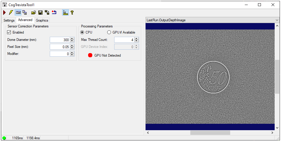
The Advanced tab offers the following controls:
| Control | Description |
Sensor Correction Parameters | Check Enabled to use specific parameters for the calculation of the Shape Horizontal and Shape Vertical images.
|
Processing Parameters | Specify additional processing parameters:
|
Use the Graphics tab to choose which image records the tool makes available in the local and floating image displays:
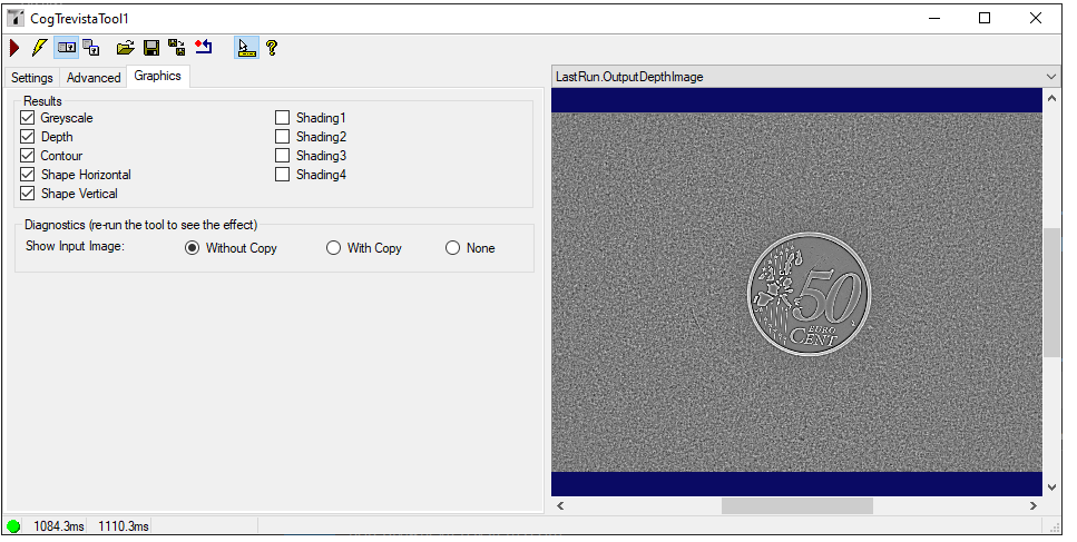
Check each type of output image you want to make available in the edit control display. Be aware the tool will not generate an image record for any given output image type if you do not also select it on the Settings tab. For example, if you enable Shape Vertical on the Graphics tab but do not select Shape Vertical in Tool Result Images on the Settings tab, there will not be a record for LastRun.OutputShapeVerticalImage in the display.
In addition, use Show Input Image to determine whether or not the input image is recorded as part of the diagnostic record, and whether the image is copied to the record or saved in the record as a reference.
The following table describes the function of each button:
| Button | Description | Function |
 | Run | Take the input CogImage8Interlaced and unpack its 8-bit pixels into four "shading" images, then process those images to produce the requested output images. |
 | Electric mode | Toggle electric mode, where the Trevista tool executes automatically when particular configuration parameters change. In electric mode, a lightning bolt appears next to every electric property. |
 | Local image display | Open or close the local image display window. A Trevista tool supports the following image buffers:
|
 | Floating image display | Open a floating image window, which supports the same image buffers as the local image display window. |
 | Open | Open a VisionPro persistence (.vpp) file that contains a set of saved properties for this vision tool object type. VisionPro reports an error if you try to open a .vpp file for another object type. |
 | Save | Save the current properties of the vision tool to a VisionPro persistence (.vpp) file. The edit control allows you to choose between saving the vision tool with or without its image buffers and tool results. |
 | Save As | Save the current properties of the vision tool to a new VisionPro persistence (.vpp) file. |
 | Reset | Reset the vision tool to its default state. The tool gives you a choice between resetting to the default-constructed state, which is appropriate when you are using it in a Visual Studio.NET application, and its template-initialized state, which is appropriate for QuickBuild applications. |
 | Show ToolTips | Enable or disable the display of tooltips for individual items in the edit control. |
 | Help | Open this VisionPro online help file. |