See the following sections to get started with an L68 series sensor:
The L68 uses the CCB-PWRIO-XX cable with the following wiring assignment:
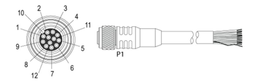
| Pin# | L68 Signal name | Wire Color |
| 1 | GND | Yellow |
| 2 | +24VDC | White/Yellow |
| 3 | IN 1 | Brown |
| 4 | OUT 2 | White/Brown |
| 5 | OUT 1 | Violet |
| 6 | ENCODER B- | White/Violet |
| 7 | ENCODER A+ | Red |
| 8 | LASER ENABLED GND | Black |
| 9 | LASER ENABLED +24VDC | Green |
| 10 | IN 2 | Orange |
| 11 | ENCODER B+ | Blue |
| 12 | ENCODER A- | Grey |
The L68 sensor starts with:
| IP Address | 192.168.178.200 |
| Subnet Mask | 255.255.255.0 |
To communicate to the sensor, you will need to configure the connected network adapter to 192.168.178.X and subnet mask 255.255.255.0. See the Microsoft Change TCP/IP Settings page for more instructions on how to configure these settings based on your version of Windows.
Once on the same network as the sensor you can either work with the sensor immediately or change the sensor’s IP using the Configure_L68_IP utility as shown:
- Open a command line window and navigate to the %VPRO_ROOT%\bin directory.
Enter the following command: Configure_L68_IP.exe
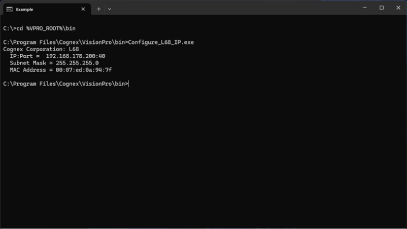
- Confirm that the MAC address of the sensor you wish to change matches the MAC address of label on the sensor.
Enter the following command: Configure_L68_IP.exe -c <current IP address of the sensor> -n <new IP address of the sensor> -s <new subnet mask of the sensor>
Note: The utility cannot discover sensors on external networks. If you choose to change the sensor to a non-default network you will need to track that new network to easily configure the IP again.
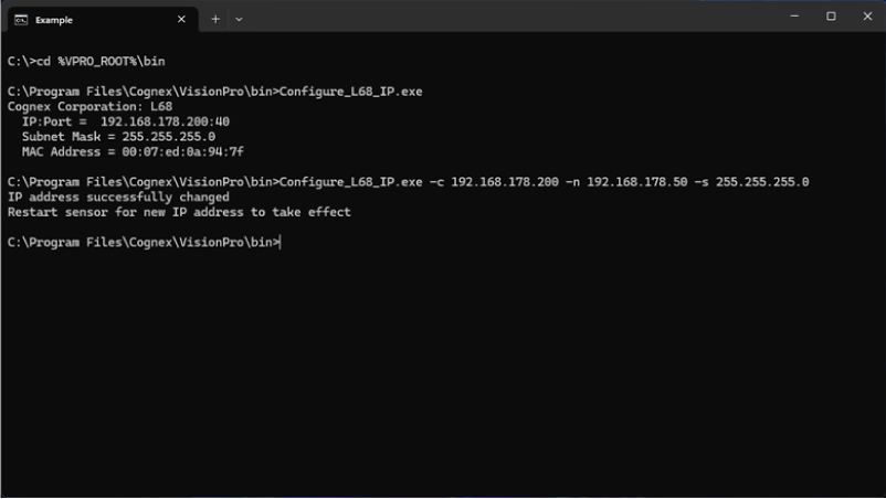
- Manually power off the sensor and then power it back on.
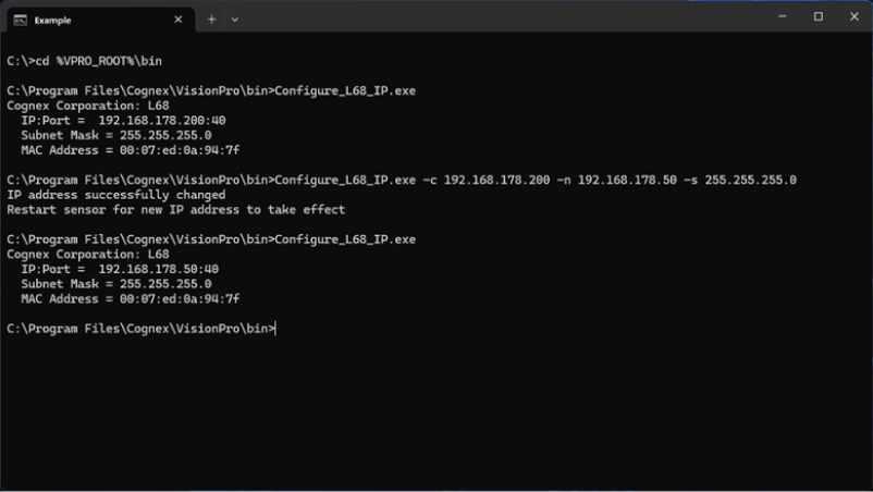
- If on the same network enter the following command: Configure_L68_IP.exe.
If not on the same network:
- Configure the connected network adapter to the new network with the previous instructions.
- Enter the following command: Configure_L68_IP.exe.
Confirm the sensor reports the new IP address.
The L68 series uses the Height,OffsetY, Width, and OffsetX values of the image to set what section of the 2D intensity image is used to generate the 3D range image. The Height and OffsetY will be set to a multiple of the ROIYIncrement and the Width and OffsetX will be set to a multiple of the ROIXIncrement based on the values you provide.
To see the area of the 2D image the ROI values will use, you can set the CameraMode to IntensityWithROI which will embed a white rectangle into the intensity image that outlines the region of interest.
To set the height of the 3D range image, use the ScanLengthInPixels custom property. The width of the 3D range image will be based on the ROI and XScale you provide.
The L68 uses custom properties to configure the device. The following is a list of the available custom properties and a description of each.
| CameraMode | Write/Read | Sets the type of data being acquired. IntensityImage for setting the ROI or Range for acquiring 3D data | Default: IntensityWithROI |
| ScanLengthInPixels | Write/Read | Sets the number of rows to acquire in a Range image | Default: 1000 |
| XScale | Write/Read | Specifies the physical size of range image pixels in the X direction (in mm/pixel) | Default: 0.006300 |
| YScale | Write/Read | Specifies the physical size of range image pixels in the Y direction (in mm/pixel). Set this value to match the distance your motion system moves between each image row. | Default: 0.100000 |
| ZScale | Write/Read | Specifies the physical size in the Z direction corresponding to one-grey-level change in the value of a range image pixel (in mm/grey-level) | Default: 0.001050 |
| MotionInput | Write/Read | Specifies whether acquisition is performed using a physical encoder, a simulated encoder, or as fast as possible (without any encoder) | Default: Encoderless |
| SimulatedEncoderFrequency | Write/Read | If MotionInput is set to SimulatedEncoder, this value specifies the frequency of the simulated encoder (in Hz) | Default: 200 |
| EncoderStepsPerLine | Write/Read | If MotionInput is set to PhysicalEncoder, this value specifies how many encoder steps occur between each line of the acquired Range image. | Default: 1 |
| IgnoreTooFastEncoder | Write/Read | Sets whether IsTooFastEncoder acqfailure can be generated due to a line overrun situation. Default is true (line overruns will not be reported) | Default: True |
| StartAcqOnEncoderCount | Write/Read | Sets the number of encoder counts to wait before acquisition starts. This property only applies when the MotionInput is set to PhysicalEncoder | Default: 0 |
| PositiveEncoderDirection | Write/Read | Specifies the scene motion that causes the encoder to generate positive-direction pulses. Set this value to LensToLaser if motion in that direction generates positive encoder pulses; otherwise, set this value to LaserToLens. | Default: LensToLaser |
| AcquireDirection | Write/Read | Specifies the scene motion for the next image acquisition. If MotionInput is set to PhysicalEncoder only motion in this direction will cause image data to be acquired. | Default: LensToLaser |
| AutoCorrectPixelRowOrder | Write/Read | Specifies whether to automatically set the row-order of the acquired image to match the actual appearance of the scene. If this value is set to False, images acquired the LaserToLens direction will appear to be mirrored top-to-bottom. | Default: True |
| HighDynamicRange | Write/Read | When true, the camera uses two different exposures to increase the dynamic range of the visible laser line. One exposure will be the requested value, and the other will be one-tenth of that. This is useful if your scene contains both dark and highly reflective regions. It also reduces the maximum line rate. | Default: False |
| Gain | Write/Read | Specifies the gain level for the acquisition. Each increase in level makes the laser line brighter without increasing the exposure time of the acquisition. It also increases the amount of noise in the image. | Default: Off |
| LaserLineIntensityThreshold | Write/Read | Specifies the minimum intensity required for a pixel to be recognized as part of the laser line. Lowering this value makes laser detection more sensitive but also more susceptible to noise. | Default: 40 |
| PeakDetectionMode | Write/Read | Specifies which laser line to use in cases where multiple lines can appear. For example, this can occur when imaging transparent objects | Default: MaxIntensity |
| ROIXIncrement | Read Only | Shows the numeric base that the pixel values of ROI parameters on the X axis must be multiples of or else be rounded. | |
| ROIYIncrement | Read Only | Shows the numeric base that the pixel values of ROI parameters on the Y axis must be multiples of or else be rounded. | |
| LineFrequency | Read Only | Shows the current line frequency. This value will internally be refreshed during acquisition. | |
| IsTooFastEncoder | Read Only | Shows if a line overrun happened during the current acquisition. | |
| EncoderStepFrequency | Read Only | Shows the actual detected frequency of the configured encoder steps. | |
| MaximumEncoderStepFrequency | Read Only | Shows the maximal possible step frequency accepted by sensor in its configuration. This register will be updated internally during acquisition of data. | |
| SensorTemperature | Read Only | Shows the internal sensor temperature in degrees Celsius. | |
| FirmwareVersion | Read Only | Shows the actual Firmware version | |
| IPAddress | Read Only | Shows the IP address of the sensor | |
| SubnetMask | Read Only | Shows the subnet mask of the sensor | |
| DefaultGateway | Read Only | Shows the default gateway of the sensor | |
| MacAddress | Read Only | Shows the MAC address of the sensor | |
| SerialNumber | Read Only | Shows the serial number of the sensor |