PMAlign Tool and Red Analyze Tool Example
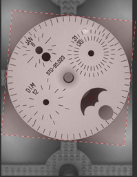
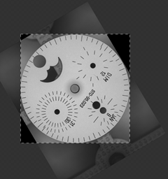
Consider these images of a watch dial:
|
|
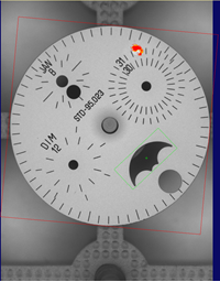
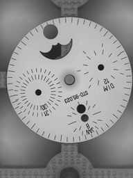
The dial's rotation is not consistent; if we want to draw a mask over the holes on the first image, that mask will not line up with the holes on the second image.
To solve this, we need to define our Red tool's ROI relative to a fixture. First, we train a PatMax tool (using the first image) to find the "crescent" shape in the dial:
PatMax produces a Pose describing how the matched pattern differs from the trained pattern. The Pose is a CogTransform2DLinear object containing scale, rotation, and translation information. Remember that the Pose is given in terms of the image's selected coordinate space; if the Pixel space is not selected, the Pose must be transformed from the selected space to Pixel space.
This Pose information is used to translate and rotate the default ROI (which is the entire image):
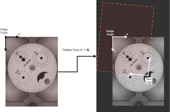
We can then edit the ROI (applying a transfrom from its default position to our desired position behind the scenes), adjusting the offset, rotation, and dimensions such that it encompasses the entire dial, but not the background:
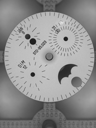
When the tool is next processed, the transformations provided by both the PatMax Pose and our adjustments are applied to the default ROI, producing a View for each training image:
|
|
Notice how the original image has rotated in the darker part of this image, while the brighter part (the View) has a constant orientation. Because of this consistency, it is now possible to draw one mask that lines up with every image.
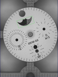
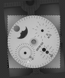
Instead of training on or processing the entire original image, the Red tool will operate on this View image instead. When the Red tool processes an image, it will create a Marking object. The Marking contains the Views the tool operated on, and any defects that the tool found within those Views. These defects will be given in View Coordinates, roughly illustrated below:
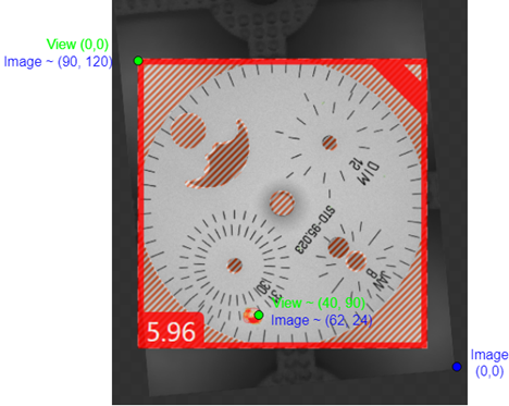
To draw this defect on the original image (with the PatMax graphics), we need to transform the defect's View Coordinates (as given by the Marking) into Image Coordinates. Then, those coordinates can be used to draw a new defect graphic using VisionPro graphic classes.
The wrapper can automatically transform ViDi graphics into VisionPro graphics. This is done by creating a RedToolRecord from the RedMarking produced by the tool. Once this Record is combined with the Record containing the PatMax graphics, the resulting image looks like this: