3D Field Calibration
The 3D Field Calibration page allows you to calibrate devices which consists of five different steps allowing for features such as barcode assignment.
Before getting started:
-
Complete the Dynamic Test page steps.
-
Make sure that the dimensioner collects the data.
-
Disconnect DataMan Bottom Side Line Scan and Image-Only readers.
This EI Box for the Vision Service Hostname and LGM-CALIBBOX-556 for the Calibration Box Type are by default selected values.
-
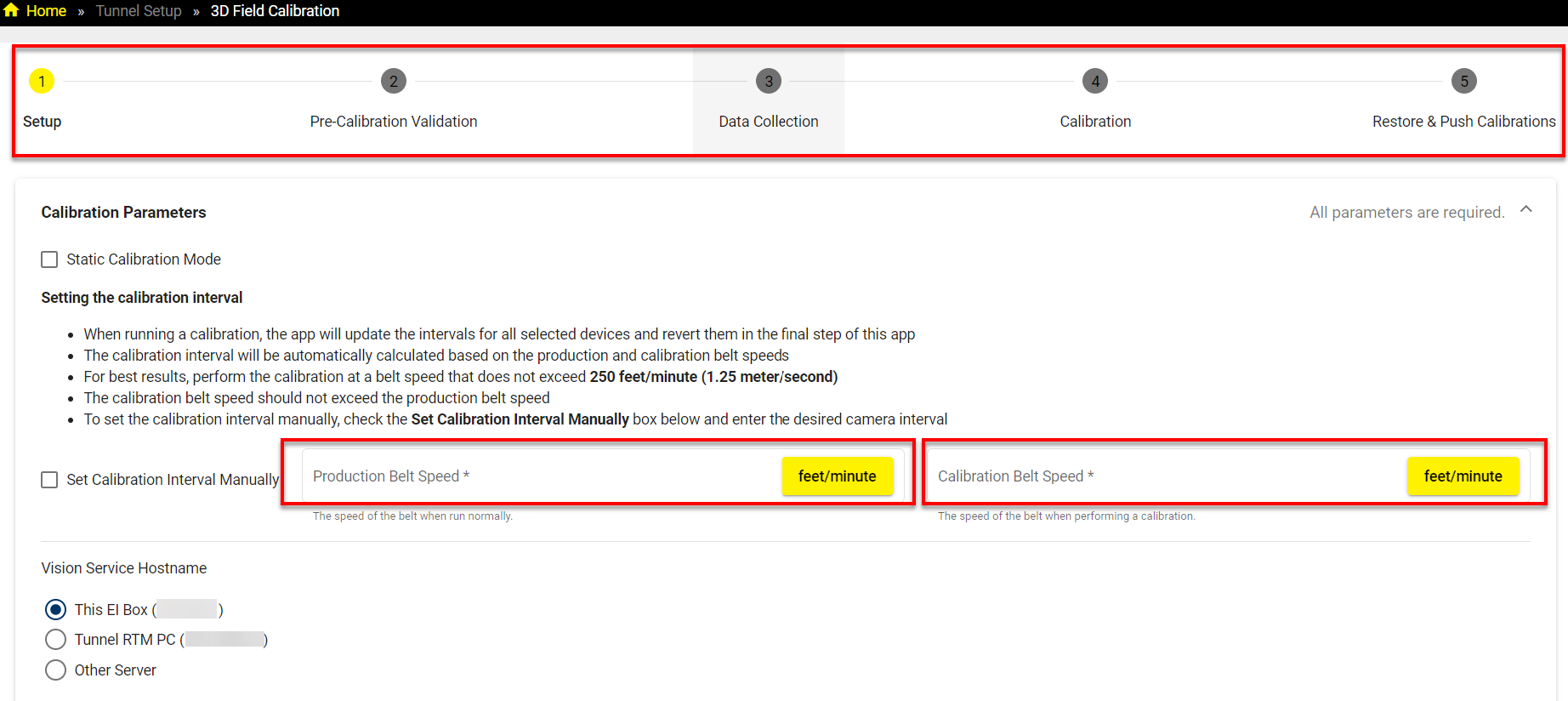
In the first step, start with setting the calibration interval. Enter conveyor parameters which are Production Belt Speed and Calibration Belt Speed and select readers:
Note: Consider the following aspects when setting the calibration interval:When running a calibration, the app updates the intervals for all selected devices and reverts them in the final step.
The calibration interval is automatically calculated based on the production and calibration belt speeds.
For best results, perform the calibration at a belt speed that does not exceed 250 feet/minute (1.25 meter/second).
The calibration belt speed must not exceed the production belt speed.
To set the calibration interval manually, check the Set Calibration Interval Manually box below and enter the desired camera interval.
Select devices to calibrate:
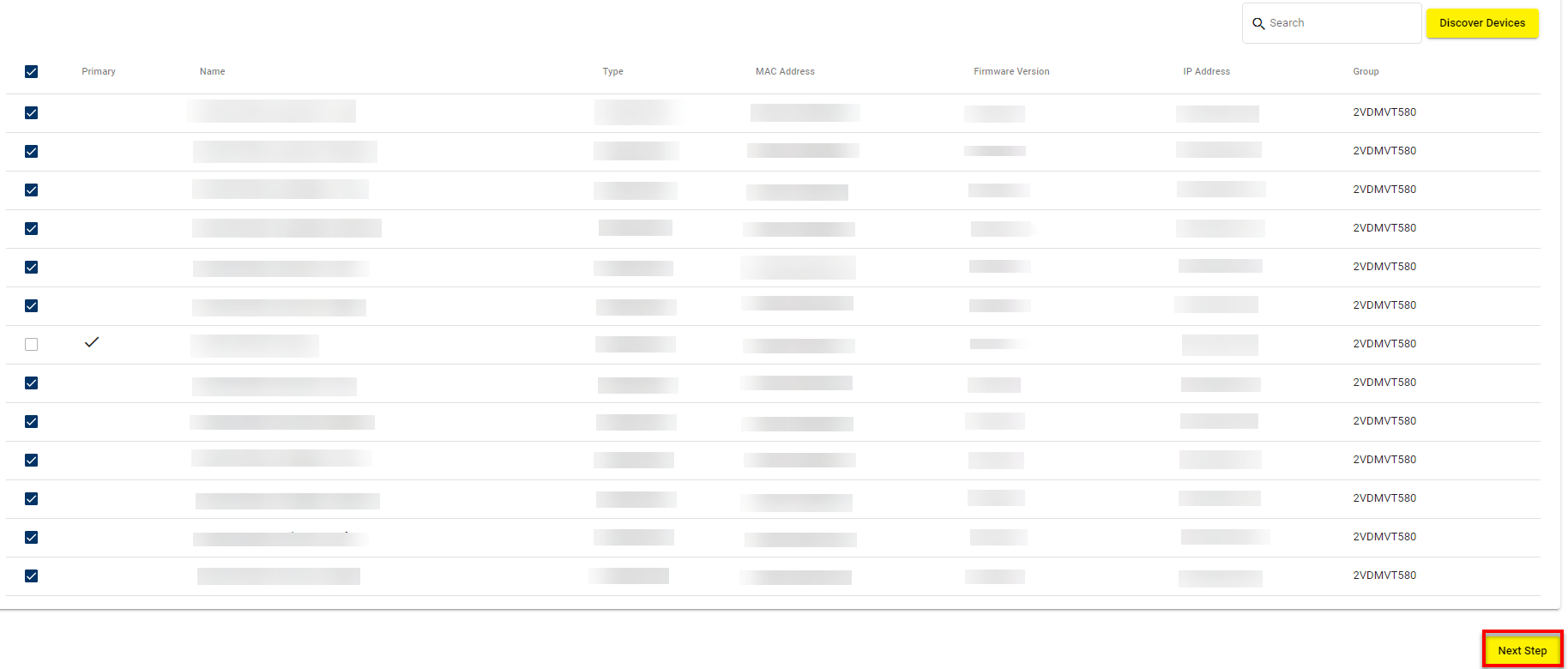
Click on Next Step to switch to the Pre-Calibration Validation step.
-
In the Pre-Calibration Validation step, validate the test parameters. After the validation is complete, the All validations successful. message appears. Click on Next Step.
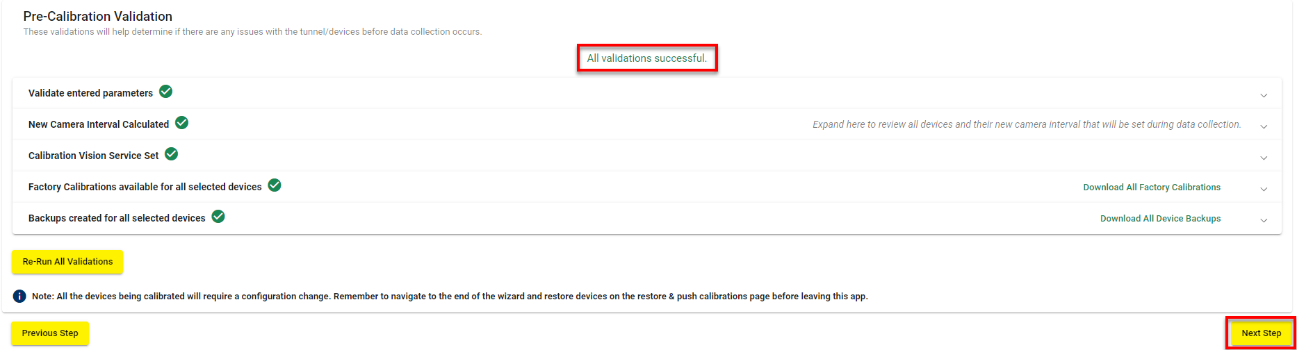 Note: If you receive an error that you cannot take backups and expanding the drop down shows an error about dirty configurations, either reload the backups taken from a previous run or re-run Tunnel Commissioning wizard.
 -
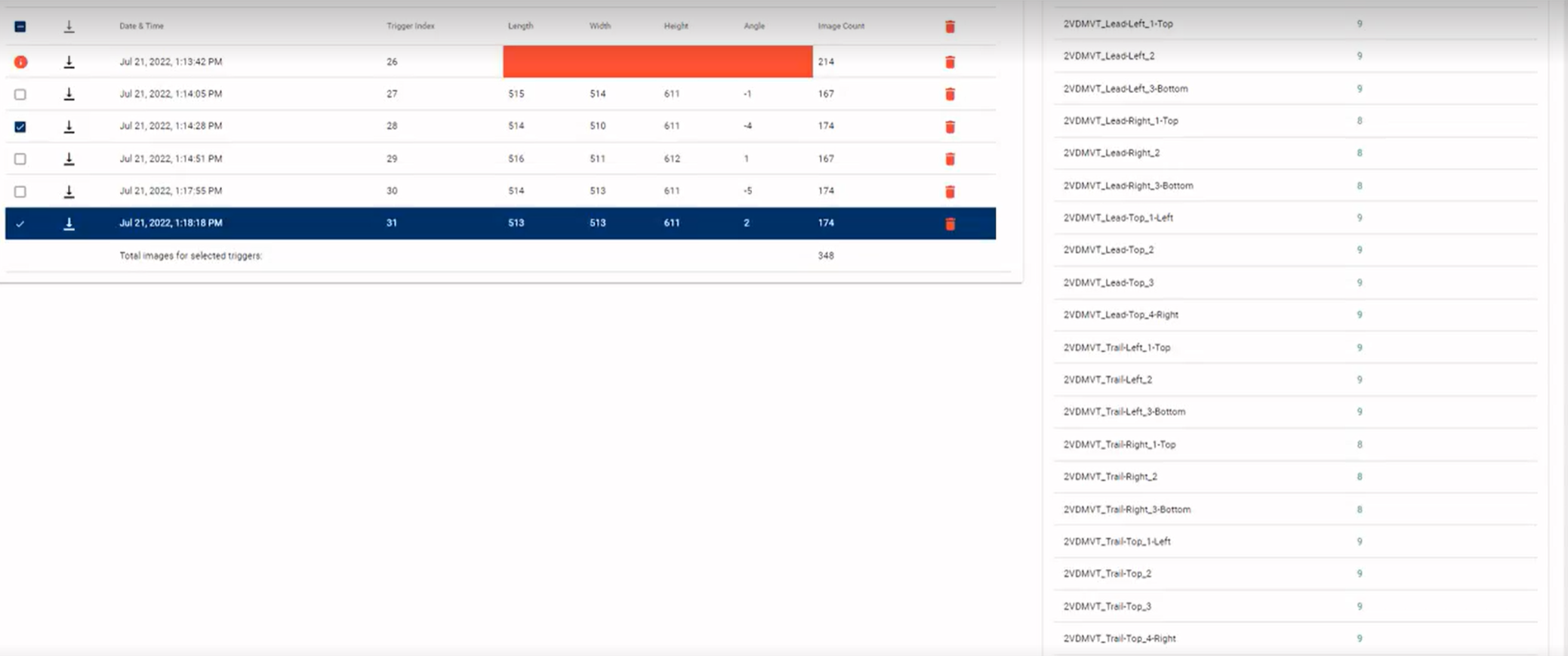
In the Data Collection step, the calibration triggers are captured.
-
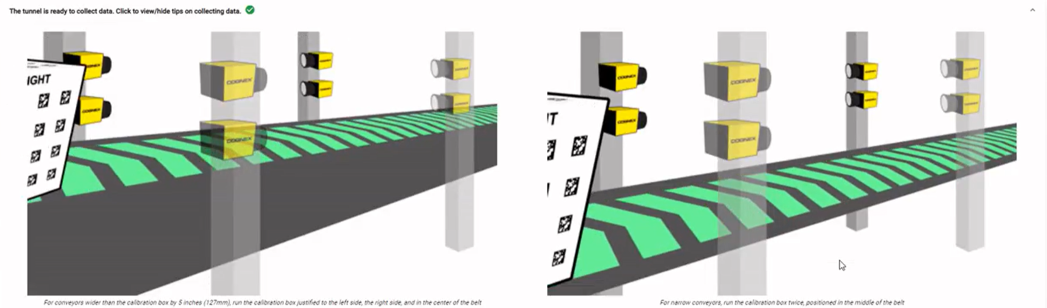
Make sure that the calibration box is oriented correctly with the front side facing downstream on the conveyor and run the box through the tunnel at the calibration speed you set in the previous step.
Note: If the conveyor is wider than the calibration box by 5 inches, you have to run the box through at different positions on the belt:The left side of the belt.
The right side of the belt.
The center of the belt.
If the conveyor is narrow, place the box at the center of the belt and run it through twice.
-
Select the best triggers from the triggers list and click on Next Step to calibrate.
-
- The Calibration step appears. Click on Re-run Failed Devices to re-run the the failed device calibrations where the calibration process begins automatically and the calibration for each device takes place.
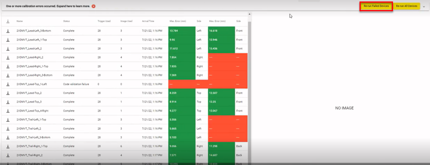
If necessary, after all the calibration is successfully complete, click on Next Step.
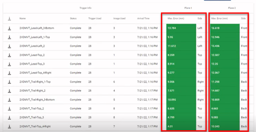
The error value columns determine if the test result is pass or fail. It is expected that error values to be higher in the right column due to higher perspective on those faces:
An optimal error value is less than 25 mm.
An acceptable error value is between 25 and 50 mm.
Any values over 50 mm are not accepted.
If you receive unacceptable values, you can return to the previous step and run another box for the area that failed by clicking on Re-run Failed Devices or Re-run All Devices.
The Complete Calibration pop-up appears. To complete the calibration, click on Confirm.
-
The final step of Restore & Push Calibrations restores the devices to their original settings and automatically load calibration data to all devices. Once this process is complete, you can close the page.