Stitch
Combines the region of interest (ROI) in multiple input images to produce a single output image. The function allows for the capturing of an entire area on a multifaceted object. For example, the Stitch function can be used to inspect the label on a rotating cylindrical object.
Stitch Inputs
| Parameter | Description | ||||||||||
|
Image |
This parameter must use Cell References in
a spreadsheet cell that contains an Image data structure. By
default, this parameter references A0, the cell containing the Image data structure returned by function. This parameter can also reference other
Image data structures, such as those returned by the Vision
Tool Image Functions |
||||||||||
| Event |
This parameter needs to be a reference to any event with a timestamp, for example, one of the following: |
||||||||||
|
Fixture |
Defines the Region of Interest (ROI) relative to a Fixture input or the output of the image coordinate system for the Vision Tools function. Setting the ROI relative to a Fixture ensures that if the Fixture is rotated or translated, the ROI is rotated or translated in relation to the Fixture. Note: 2D projections use real world units but fixturing with 2D tools requires input in pixel values. When using a 2D projection from a 3D point cloud as a Fixture, convert the real world units to pixel values using the TransWorldToPixel function.
The default setting is (0,0,0), the top leftmost corner of the image.
|
||||||||||
|
Region |
Also known as the Region of Interest (ROI), specifies the region of the image that undergoes analysis. Double-click on the Region parameter to create an Interactive Graphics Mode that you can transform and rotate. Select this parameter and press the Maximize Region button on the Job Edit toolbar of the property sheet to automatically stretch the region to cover the entire image.
|
||||||||||
| Pixel shift X |
Specifies the horizontal shift between sequential images, in pixels. |
||||||||||
| Pixel shift Y |
Specifies the vertical shift between sequential images, in pixels. |
||||||||||
| Stitches per output image | Specifies the number of images that compose the output image. | ||||||||||
| Reset |
Clears the input image. Note: When doing a continuous stitch job, it is not necessary to reset the initial input image.
|
||||||||||
|
Show |
Specifies which graphical overlays are displayed on top of the image.
|
Stitch Outputs
|
Returns |
An Image data structure containing the processed image, or #ERR if any of the input parameters are invalid. |
Stitch Example
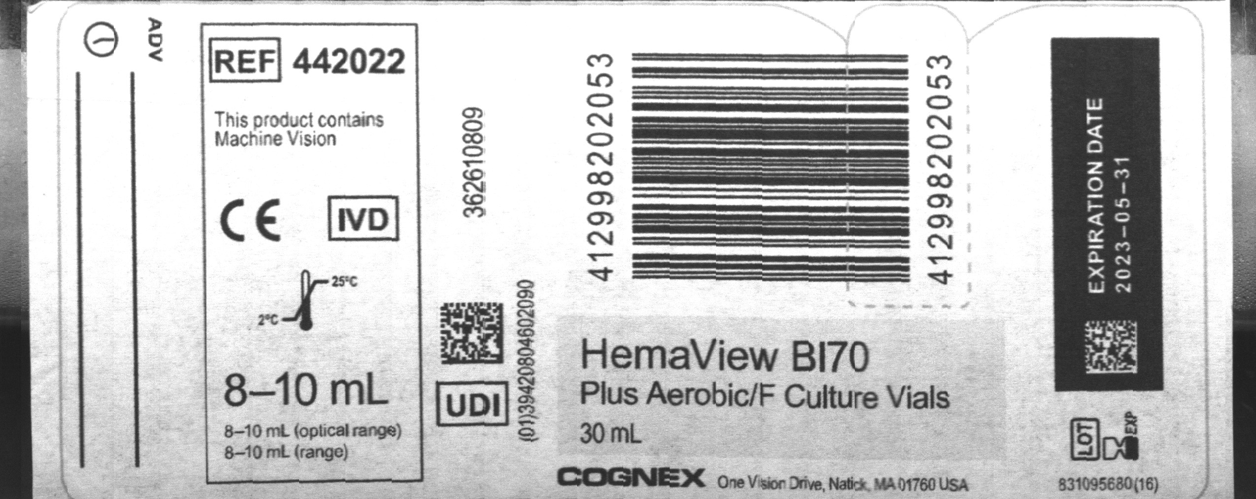
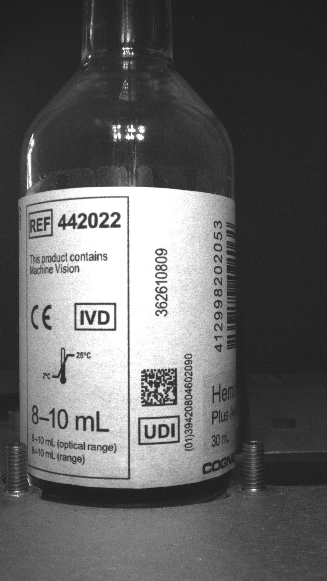
In this example job, the object in the input image is a bottle. The purpose of this example is to stitch together multiple images into one image.
-
Insert the Stitch function into the In-Sight Spreadsheet spreadsheet.
-
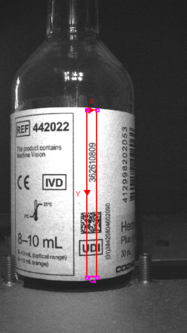
Define the ROI by double-clicking on Region in the property sheet, which disappears to reveal the red ROI box overlaid on the image. Move or resize the box using the cursor.
-
Set the size of the output image by defining the Pixel shift X or Pixel shift Y. For example, when stitching a vertical image, set the Pixel shift X parameter per shift.
Tip: It is recommended to use the Pattern Match functions to find the Pixel shift value. -
Set the Stitches per output image, which defines how many images are stitched together.
Note: The height of the output image is the number of images selected, multiplied by the Pixel shift. If the Pixel shift value is bigger than the height value of the input image, errors may appear in the output image.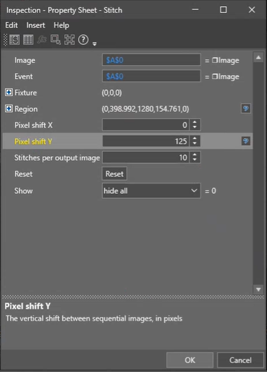
-
Click OK on the Job Edit toolbar to confirm the selection and return to the property sheet.
Tip: You can also confirm by pressing the Enter key or by double-clicking within the ROI. -
Individually select the images to be stitched together.
The value for Complete changes from 0.000 to 1.000 when the Stitch function is complete. The function creates an output image.
Note: Stitched images do not consume an image buffer.