Writing Data from the PLC to the Vision System
In order to send data from the Siemens PLC to the In-Sight Spreadsheet spreadsheet, the data must be pulled from the PROFINET stack by using the ReadUserDataBuffer function. ReadUserDataBuffer function takes the data format created within the FormatInputBuffer function, reads the data from the data area of the PROFINET User Data module, and formats this data into the In-Sight Spreadsheetspreadsheet. The PLC receives data at every update cycle.
Workflow example
- Open the AcquireImage cell and set the Trigger parameter to Continuous.
- Right-click an empty cell and select Insert Function to open the Insert Function dialog. From the left pane, click the Input/Output category, then double-click the FormatInputBuffer function, from the right pane, to insert it into the spreadsheet.
-
From the FormatInputBuffer dialog, click the Add button and add a 32-bit float and a 32-bit integer to the list.
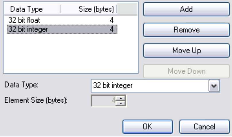
- Close the FormatInputBuffer dialog by clicking the OK button.
- Right-click an empty cell and select Insert Function to open the Insert Function dialog. From the left pane, click the Input/Output category, then double-click the ReadUserDataBuffer function from the right pane, to insert it into the spreadsheet .
- Set the Protocol parameter of the ReadUserDataBuffer function to PROFINET, and the Buffer parameter as a cell reference to the recently created Buffer data structure of the FormatInputBuffer function.
- Add the GetBufferData function to the spreadsheet based on the fields you specified in the FormatInputBuffer function.
- Set the In-Sight vision system Online.
- In Simatic Manager, create a new Variable Table by right-clicking on your PLC and selecting Variable Table from the Insert New Object menu.
-
Open the new table and add four items, two for the sent user data, and two for SetUserData and SetUserDataAck:
Offset Address Display Format 0 PID 257 FLOATING_POINT +4 PID 261 DEC Q1.2 BOOL I4.7 BOOL Note: The addresses assume that the User Data Module is at output address 257. If the User Data Module is at a different address, apply the specified offset to the output address to set the correct address. -
In the Simatic Manager, click on the PLC > Connect To > Configured PLC menu.
-
Enter values for the four items added to the Variable Table and then select Activate Modify Values from the Variable menu.
-
After entering the values, set the SetUserData bit, wait for the SetUserDataAck bit to be set, and then clear the SetUserData bit.
-
The values in the In-Sight Spreadsheet change to the entered values.