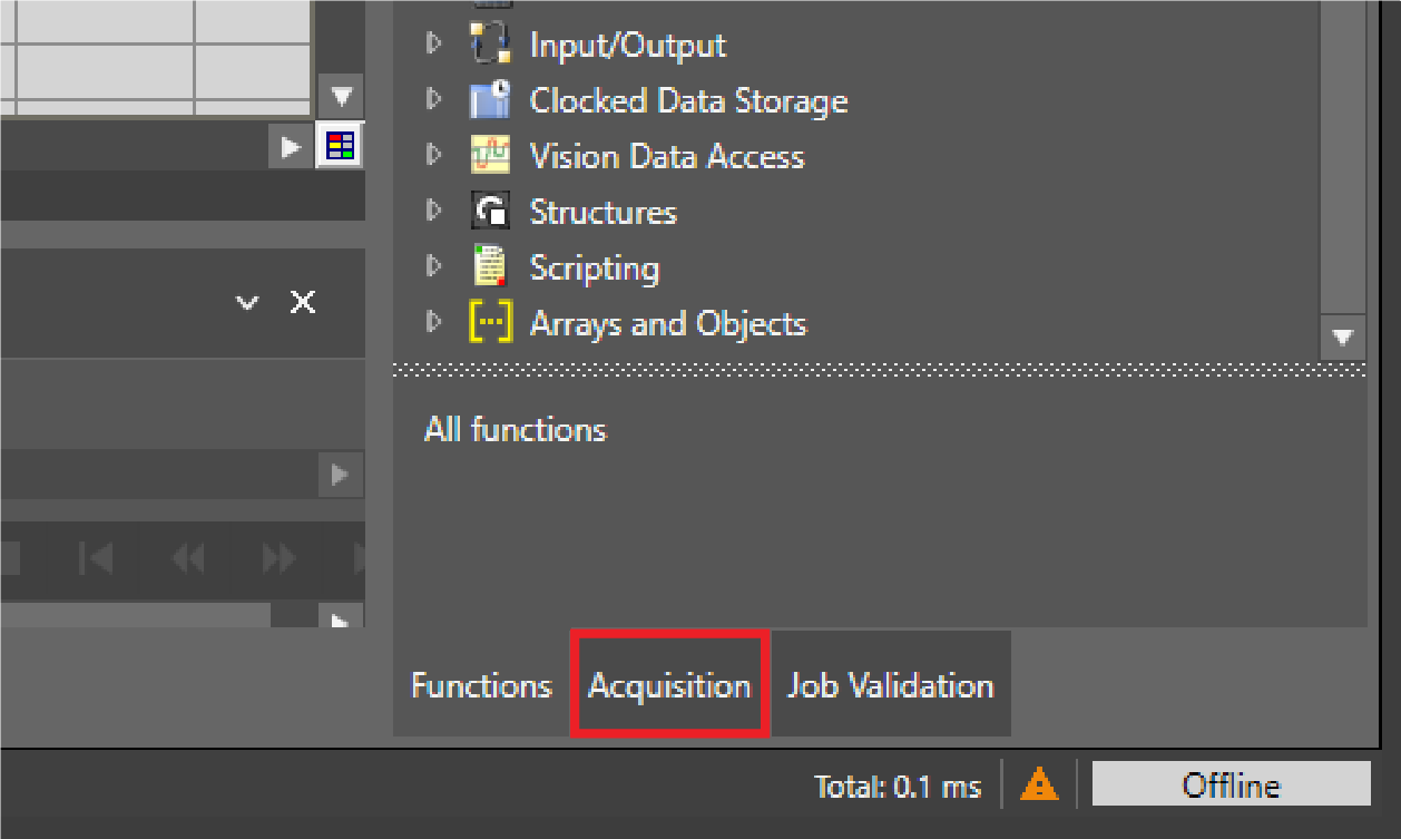
Acquisition Panel
Use the Acquisition Acquisition is the process or result of the vision system acquiring a new image. panel to adjust settings for the next image acquisition. To open the panel, click Acquisition in the bottom right corner.
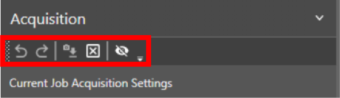
Acquisition Panel Actions
The following table describes the icons at the top of the
|
|
|
|---|---|
| Icons | Action |
|
|
Undo last action. |
|
|
Redo last action. |
|
|
Reset settings to the values that were in use when you first connected to the vision system. |
|
|
Reset acquisition settings to the default values. |
|
|
Show or hide settings that currently have no effect. |


Acquisition Settings
Use the acquisition settings to configure how the vision system acquires images. Some settings only appear in the user interface when you are connected to specific vision system models, such as
The following table describes the trigger settings available on the
| Setting | Description |
|---|---|
| Trigger Type |
Defines the type of trigger signal that begins an image acquisition. The following options are available:
|
|
Trigger Interval (ms) |
Defines the time in milliseconds between acquisitions when Self trigger type is selected. The available values are 0–10000. Note: Appears only when Trigger Type is set to Self.
|
|
Trigger Source |
Defines the trigger source for the acquisition. The following trigger sources are available:
Note: Appears only when Trigger Type is set to Single.
|
|
Debounce (ms) |
Defines the time in milliseconds that a trigger has to last to trigger an acquisition. The available values are 0–10. Note: Appears only when Trigger Type is set to Single.
|
|
Delay (ms) |
Defines the delay between the time that the vision system receives a trigger to acquire an image, and the time the vision system begins the image acquisition. The available values are 0–10000. Note: Appears only when Trigger Type is set to Single.
|
The following table describes the imaging mode settings available on the
| Setting | Description | ||||||||
|---|---|---|---|---|---|---|---|---|---|
| Mode |
Specifies the imaging mode to use for acquisition. The following options are available:
|
The following table describes the general settings available on the
| Setting | Description |
|---|---|
| Exposure (ms) |
Defines the exposure time. When the vision system receives an image acquisition trigger signal, light is integrated into the image sensor array for the specified duration. The minimum value is 0. The maximum value depends on the capabilities of the connected integrated lighting accessory. If no integrated lighting accessory is connected, the limit defaults to the capabilities of the imager. Note:
With an Intensity value above 100 for external Cognex Ecosystem LightCognex Ecosystem Lights are lights that you can manage directly within In-Sight Vision Suite. Once they are connected to an In-Sight vision system or vision controller, you can discover, configure, and control them in the Acquisition or Image panel.s, the maximum duty cycle the light can support can change. If the supported duty cycle is not compatible with the Exposure (ms) time, brightness might not increase. A warning is displayed in this case. |
| Override Max Exposure |
Allows setting the exposure time to values greater than the recommended maximum. When enabled, if the exposure time exceeds the capability of the illumination accessory, the illumination accessory does not remain on during the entire exposure. The following options are available:
Note:
This setting is not available on In-Sight 6900 series vision controllers. |
| Offset |
Brightens the image additively. Enhances dark areas but loses detail on bright spots. Most useful when combined with Gain Factor. The available values are 0–255. |
| Gain Factor |
Brightens the image multiplicatively. Enhances dark areas but reduces detail in bright regions and increases image noise. For best results, combine this setting with Offset. The available values are 1–251.18. To adjust the value, use the following methods:
|
| Orientation |
Defines the orientation at which the vision system processes the acquired image. The following options are available:
|
| Image Buffers |
Defines the number of image buffers allocated for acquisition. The available values are 6–25. Considerations for setting the image buffer:
Note: When in Single Trigger mode, if a trigger is received but no buffer is available for image acquisition, the image acquisition does not occur. In addition, if a Discrete Output line is configured to use ERR: Missed Acquisition, this signal is raised for each acquisition until a buffer becomes available.
|
The following table describes the line scan settings available for the In-Sight 3800 Line Scan vision system models:
| Setting | Description | |||||||||||||||||||||||||||||||||||||||||||||||||||||||||||||||||||||||||||||||||||||||||||||||||||||||||||||||||||||||||||||||||||||||||
|---|---|---|---|---|---|---|---|---|---|---|---|---|---|---|---|---|---|---|---|---|---|---|---|---|---|---|---|---|---|---|---|---|---|---|---|---|---|---|---|---|---|---|---|---|---|---|---|---|---|---|---|---|---|---|---|---|---|---|---|---|---|---|---|---|---|---|---|---|---|---|---|---|---|---|---|---|---|---|---|---|---|---|---|---|---|---|---|---|---|---|---|---|---|---|---|---|---|---|---|---|---|---|---|---|---|---|---|---|---|---|---|---|---|---|---|---|---|---|---|---|---|---|---|---|---|---|---|---|---|---|---|---|---|---|---|---|---|---|
| Line Trigger Type |
Defines the type of encoder. The following options are available:
|
|||||||||||||||||||||||||||||||||||||||||||||||||||||||||||||||||||||||||||||||||||||||||||||||||||||||||||||||||||||||||||||||||||||||||
| Line Period |
Defines the time for each image line in microseconds. The available values are 0–1000000. Cognex recommends the following line period settings to avoid line overrun, depending on the resolution mode:
Note: If you select a value that exceeds the maximum line period for a given exposure, the line period is automatically set to the fastest possible value.
Note: Only available when Line Trigger Type is set to Software Encoder.
|
|||||||||||||||||||||||||||||||||||||||||||||||||||||||||||||||||||||||||||||||||||||||||||||||||||||||||||||||||||||||||||||||||||||||||
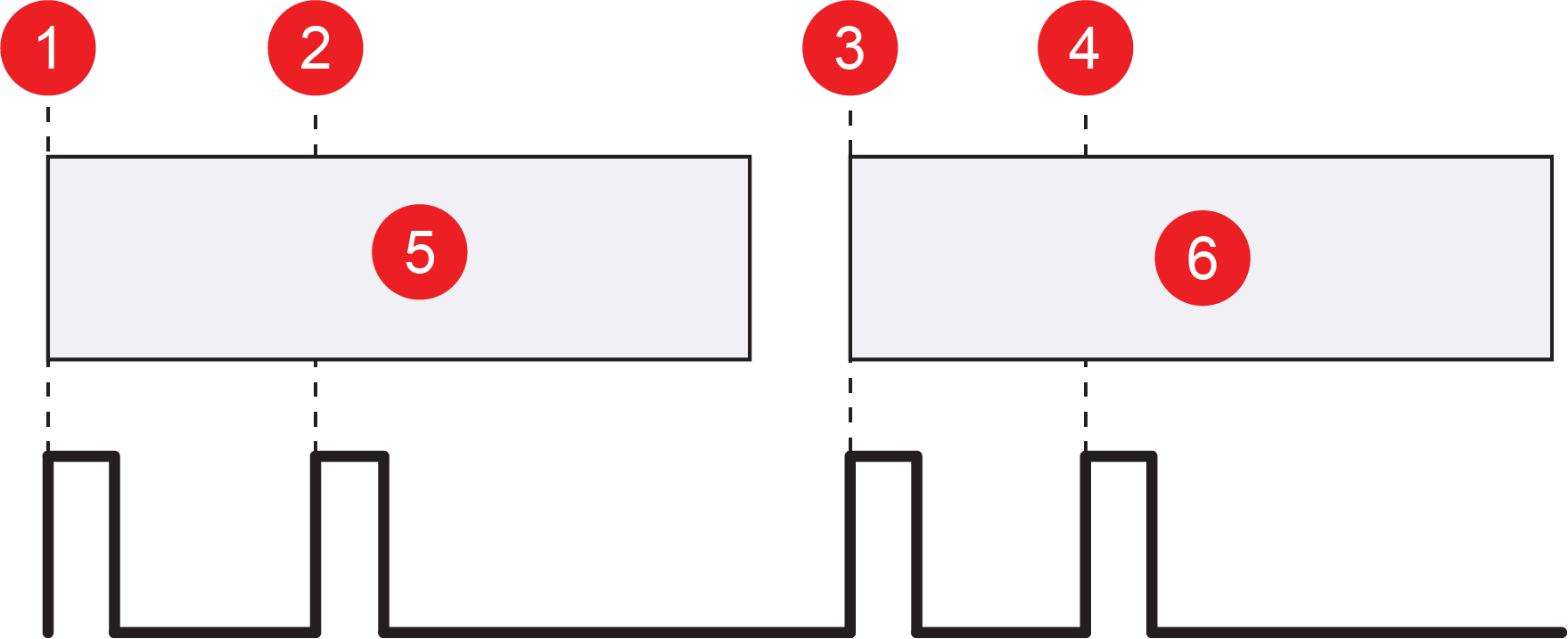
| Steps Per Line |
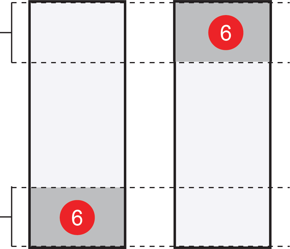
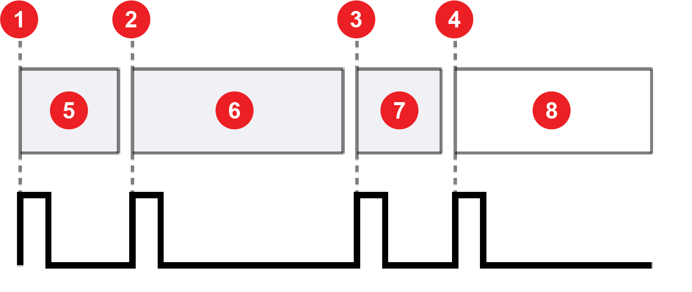
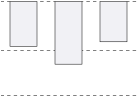
Defines the number of encoder steps for each image line. A step is a complete cycle of the encoder signal or signals, depending on the encoder you use. For a single-line hardware encoder, a complete cycle is equivalent to two signal transitions. For a quadrature hardware encoder, a complete cycle is equivalent to four signal transitions. The following image shows how steps per line correlate to signal transition for different encoders:
The available values are 0.25–4000000. Note: Increment by 0.5 for single-line hardware encoders, and by 0.25 for quadrature hardware encoders.
Note: The Steps Per Line parameter is only available when the Line Trigger Type is set to Hardware Encoder.
|
|||||||||||||||||||||||||||||||||||||||||||||||||||||||||||||||||||||||||||||||||||||||||||||||||||||||||||||||||||||||||||||||||||||||||
| Encoder Type |
Defines the type of hardware encoder used to trigger line acquisitions. The following options are available:
|
|||||||||||||||||||||||||||||||||||||||||||||||||||||||||||||||||||||||||||||||||||||||||||||||||||||||||||||||||||||||||||||||||||||||||
| Direction |
Defines the forward direction of the quadrature encoder. The vision system uses the Direction to determine the correct operating direction. The following options are available:
Reversing the direction during image acquisitionAcquisition is the process or result of the vision system acquiring a new image. stops the acquisition. You can continue the acquisition when the vision system reaches the saturation boundary by advancing forward back to the original position. Note: Only available when Encoder Type is set to Quadrature.
|
|||||||||||||||||||||||||||||||||||||||||||||||||||||||||||||||||||||||||||||||||||||||||||||||||||||||||||||||||||||||||||||||||||||||||
| Clip Mode |
Specifies an action if an image acquisition trigger is received, but the specified number of lines have not yet been acquired. The following options are available:
|
|||||||||||||||||||||||||||||||||||||||||||||||||||||||||||||||||||||||||||||||||||||||||||||||||||||||||||||||||||||||||||||||||||||||||
| Acquisition Duration |
Specifies when to end image acquisition if the Clip Mode is set to Fill Black or Reduce Image. The following options are available:
Note: The End of Trigger mode can only be used with the Reduce Image clip mode.
|
|||||||||||||||||||||||||||||||||||||||||||||||||||||||||||||||||||||||||||||||||||||||||||||||||||||||||||||||||||||||||||||||||||||||||
| Encoder Trigger Delay |
Specifies a delay to the trigger in encoder steps. Up to 18 triggers can be queued within the delay. |
|||||||||||||||||||||||||||||||||||||||||||||||||||||||||||||||||||||||||||||||||||||||||||||||||||||||||||||||||||||||||||||||||||||||||
| Encoder Acquisition Timeout |
Defines the maximum amount of time to acquire an image in milliseconds. If the vision system does not complete image acquisition within the specified time, the vision system aborts the acquisition and an issues Acquisition Error. The available values are 0–10000. The default value 0 means that the timeout is disabled. |
|||||||||||||||||||||||||||||||||||||||||||||||||||||||||||||||||||||||||||||||||||||||||||||||||||||||||||||||||||||||||||||||||||||||||

The following table describes the image size settings available on the
| Setting | Description |
|---|---|
| Start Row |
Defines the first row to transfer from the image sensor into the memory of the vision system. The available values depend on the configured resolution of the vision system. Note: For area scan models, values must be divisible by 4.
|
| Number of Rows |
Defines the number of image sensor rows to transfer into the memory of the vision system. The available values depend on the configured resolution of the vision system. Note: For area scan models, values must be divisible by 4.
|
| Number of Rows (Line Scan) |
Defines the number of lines to acquire to create the full line scan image. The available values are 8–16376, but not all values are valid. The spreadsheet user interface marks invalid values with a red exclamation point. To determine valid values, do the following calculation:
The smallest practical value is 8, so 8, 20, 32, ..., 16376 are valid values. Note: If you choose a smaller frame length option in the Camera Configuration utility, the maximum number of rows decreases accordingly.
|
| Start Column |
Defines the first column to transfer from the image sensor into the memory of the vision system. The available values depend on the resolution of the connected vision system and the Number of Columns value. The value must be divisible by 4. Note:
This setting is only available on In-Sight 6900 series vision controllers. |
| Number of Columns |
Defines the number of image sensor columns to transfer into the memory of the vision system. The available values depend on the resolution of the connected vision system. The value must be divisible by 4. Note:
This setting is only available on In-Sight 6900 series vision controllers. |
The following table describes the illumination settings available on the
Keep the following in mind for illumination settings for In-Sight 6900 series vision controllers and Cognex Ecosystem LightCognex Ecosystem Lights are lights that you can manage directly within In-Sight Vision Suite. Once they are connected to an In-Sight vision system or vision controller, you can discover, configure, and control them in the Acquisition or Image panel.s:
-
In-Sight 6900 series vision controllers only support external lighting.
-
Illumination settings, besides Mode and Detect Lights, are only shown in In-Sight Spreadsheet when a supported Cognex Ecosystem Light is connected and detected.
-
If no light, or a light that is not a Cognex Ecosystem Light is connected, the additional illumination settings are not shown. The vision controller still outputs a strobe signal on the lighting port. This provides basic compatibility with third-party lighting accessories.
-
Detection of Cognex Ecosystem Lights is supported only on the In-Sight 3800 series vision systems, the In-Sight 3900 series vision systems, and the In-Sight 6900 series vision controllers.
| Setting | Description |
|---|---|
| Mode |
Defines the illumination device. The following options are available:
|
| Detect Lights |
Click Detect Lights to identify any connected Cognex Ecosystem Lights supported by your vision system or vision controller. This option is available only if the illumination Mode is set to External Illumination and the vision system is configured for Cognex Ecosystem Lights. Check the Light Port Configuration setting in the Camera Configuration utility in In-Sight Vision Suite. If the vision system is configured for Analog Intensity (0–10V), the Detect Lights button does not detect Cognex Ecosystem Lights and shows an error message. If a supported Cognex Ecosystem Light is detected, its configuration options appear under the Detected Lights section. Note: In the 26.1.0 release of In-Sight, the Detect Lights button is not available for In-Sight 6900 series vision controllers because they do not support hot-swapping Cognex Ecosystem Lights. This means that In-Sight Spreadsheet does not detect the lights if they are connected while the vision controller is powered. To ensure the illumination settings appear, power down the vision controller before connecting any devices.
|
| Intensity |
Specifies the intensity of the illumination device. The available values are 0–100. Note:
For external Cognex Ecosystem Lights, the Intensity setting appears under Detected Lights. |
| Always On |
When enabled, the illumination device is on continuously. The following options are available:
Note:
For external Cognex Ecosystem Lights, the Always On settings appears under Detected Lights if the detected light supports this setting. |
| Strobe Start |
Defines when the strobe fires. The following options are available:
Note:
The Strobe Start setting appears depending on the following:
|
| Strobe Polarity |
Defines the signal that fires a connected strobe. The following options are available:
Note:
The Strobe Polarity setting appears depending on the following:
|
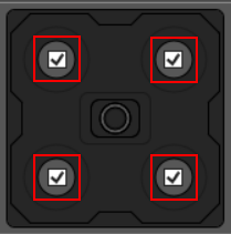
| Banks Enabled |
Check or uncheck the checkboxes inside the banks on the graphic to enable or disable each bank.
Banks graphics can vary depending on the illumination hardware attached to the vision system. Note: Appears only when Mode is set to Integrated Illumination.
|
| Light Color |
Defines the color of the illumination. The following options are available:
Note: Appears only when Mode is set to Integrated Illumination.
|
The following table describes the details and settings related to the Cognex Ecosystem LightCognex Ecosystem Lights are lights that you can manage directly within In-Sight Vision Suite. Once they are connected to an In-Sight vision system or vision controller, you can discover, configure, and control them in the Acquisition or Image panel. available on the
| Setting | Description |
|---|---|
| Model Name | Displays the details of the detected Cognex Ecosystem Light. |
| Serial Number | |
| Part Number | |
| Light Color | |
| Firmware Version | |
| Update Firmware |
Click Update Firmware to update the firmware on the connected Cognex Ecosystem Light. This option is only available if the update firmware is newer than the firmware of the vision system or vision controller. |
| Intensity |
Specifies the intensity of the illumination LED banks as a percentage. The available values are 0–300. The setting behaves the following way depending on the values and other settings:
Note:
With an Intensity value above 100 for external Cognex Ecosystem Lights, the maximum duty cycle the light can support can change. If the supported duty cycle is not compatible with the Exposure (ms) time, brightness might not increase. A warning is displayed in this case. |
| Always On |
Defines the work mode of the attached lights. This setting is only available if the attached light supports both options. The following options are available:
|
The following table describes the focus settings, which are available when a liquid lens is attached to the vision system:
| Setting | Description |
|---|---|
| Focus Distance (mm) |
Focus distance in millimeters. The available values are 65–4043. |
| Focus Region |
Defines the size and position of lens focus region. Click on the Edit button to set. |
| Autofocus |
A single button to auto-set the focus position based on current settings. |
This setting is not available on In-Sight 6900 series vision controllers.
The following table describes the High Dynamic Range (HDR) settings available on the
| Setting | Description |
|---|---|
| HDR Mode |
Enables or disables High Dynamic Range (HDR) processing. The following options are available:
Note:
HDR+ is only available on IS3800 models. HDR is not available on color units.
|
This setting is not available on In-Sight 6900 series vision controllers.
The following table describes the White BalanceWhite balance refers to the color temperature at which white objects on the image actually look white. settings available on the
| Setting | Description |
|---|---|
| Red |
Defines the red white balance gain value. The available values are 1–255. |
| Green |
Defines the green white balance gain value. The available values are 1–255. |
| Blue |
Defines the blue white balance gain value. The available values are 1–255. |
| White Balance Region |
Defines the size and position of lens focus region. Click on the Edit button to set. |
| White Balance |
Click White Balance to set the white balance of the acquired image automatically. The vision system sets the white balance based on the White Balance Region. |
White Balance settings are only available for color vision systems and GigE cameras connected to In-Sight 6900 series vision controllers.