Triggering from the PLC
The following image shows the rungs for triggering from the PLC:
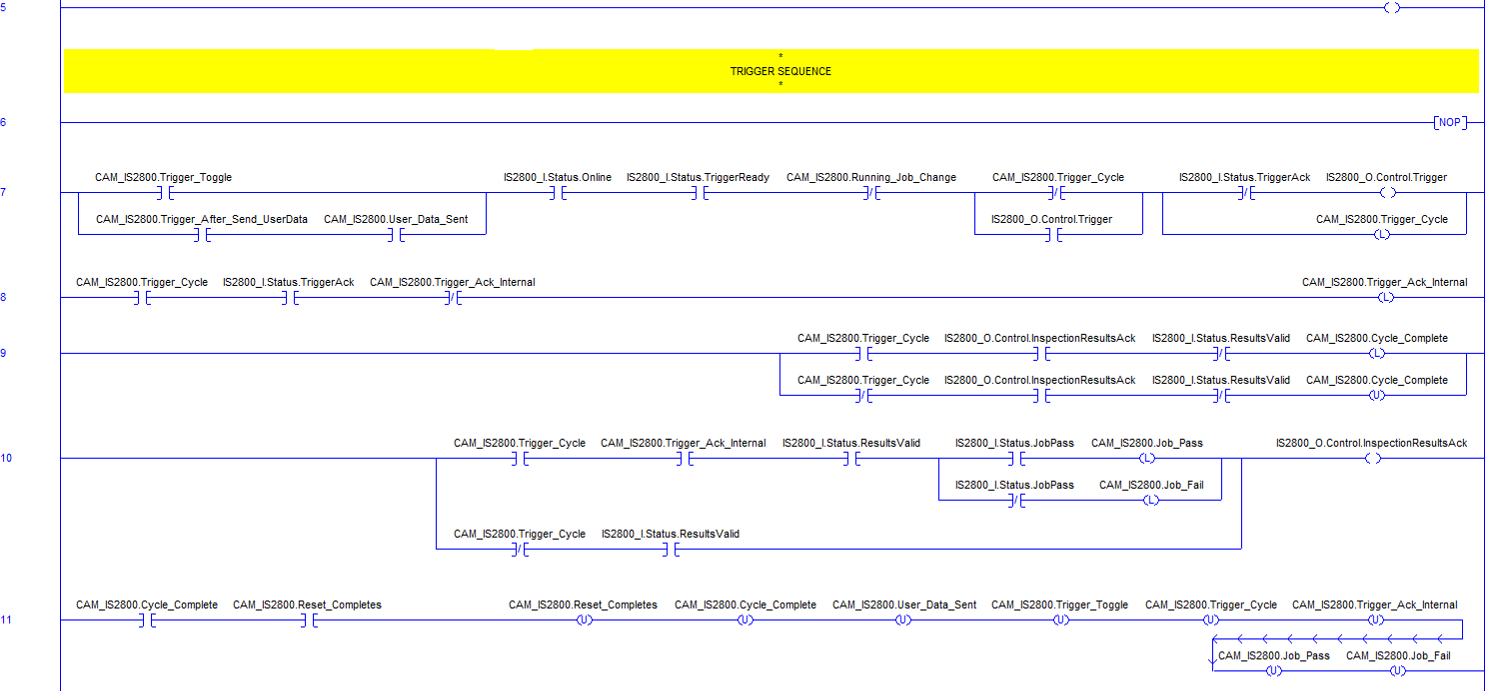
Rung 5: sets the TriggerEnable bit to 1 to enable triggering the vision system. If it is cleared to 0 and the Trigger bit is set to 1 an error occurs.
Rungs 6 -11: encapsulate the trigger sequence.
Rung 7: initiates the trigger sequence by manually setting the CAM_IS2800.Trigger_Toggle bit to 1. Only 1 trigger or image acquisition occurs using this PLC logic.
The PLC logic expects the vision system to be in the online state (Online bit - XIC, Examine closed), TriggerReady bit set to 1 (TriggerEnable set and online sets this bit to 1), and similar to above checks the interlock bits that CAM_IS2800.Running_Job_Change is cleared to 0, CAM_IS2800.Trigger_Cycle is cleared to 0 (not already in a trigger cycle), and the TriggerAck bit is cleared to 0 in order to trigger the vision system by setting the Trigger bit to 1 and then latching the CAM_IS2800.Trigger_Cycle bit so job change or setting User Data cannot run until the trigger cycle completes.
The branch around the CAM_IS2800.Trigger_Cycle bit containing the Trigger bit is for "sealing in" the logic so the Trigger bit stays on until TriggerAck is received. Once TriggerAck is set to 1 in the vision system, this causes the logic to reset the Trigger bit to 0.
Optionally the branch around the CAM_IS2800.Trigger_Toggle bit can automatically trigger the vision system after sending User Data by manually setting the CAM_IS2800.Trigger_After_Send_UserData bit to 1 and the CAM_IS2800.User_Data_Sent is set above in rung 4 once the User Data is written to the vision system.
Rung 8: latches an internal bit CAM_IS2800.Trigger_Ack_Internal to 1 once the trigger cycle is started (set to 1 in above rung), the vision system returns TriggerAck set to 1 and checks that CAM_IS2800.Trigger_Ack_Internal is not already set to 1. The CAM_IS2800.Trigger_Ack_Internal bit is used later as a condition to read results as a result of the trigger in this trigger cycle.
Rung 9: latches the CAM_IS2800.Cycle_Complete bit to 1 if we are in the trigger cycle (trigger was initiated in this logic) by checking that CAM_IS2800.Trigger_Cycle is set to 1, The InspectionResultsAck bit is set to 1 and ResultsValid is cleared to 0 (results were read into the PLC). If the trigger was initiated from a manual trigger or WebHMI the CAM_IS2800.Trigger_Cycle bit could be cleared to 0 and the branch around the logic above could run and cause the CAM_IS2800.Cycle_Complete bit to be unlatched to 0.
Rung 10: reads the results and job pass or fail state and latch the internal pass or fail bits depending on if CAM_IS2800.Trigger_Cycle and CAM_IS2800.Trigger_Ack_Internal bits are set to 1. It also performs the handshaking of the ResultsValid bit when it is set to 1 by the vision system and then the PLC sets the InspectionResultsAck bit 1 to clear which clears the ResultsValid bit in the vision system and when that is cleared to 0 clears the InspectionResultsAck bit to 0. When the results are not from a trigger sent from the CAM_IS2800.Trigger_Cycle being set to 1, only the handshaking of the ResultsValid and InspectionResultsAck occur so ResultsValid is cleared to 0 in either case.
Rung 11: clears (unlatches) all of the internal bit states set in the prior rungs once the CAM_IS2800.Cycle_Complete bit is set to 1 (rung 9) and the manual setting of the CAM_IS2800.Reset_Completes bit to 1 occurs by the you. No more triggers can be sent from the PLC until CAM_IS2800.Reset_Completes bit is set to 1 to initialize the PLC logic back to the original ready for triggering state. Sending of User Data also does not occur until the manual setting of CAM_IS2800.Reset_Completes bit to 1 occurs (CAM_IS2800.User_Data_Sent unlatched to 0).