Raw 2D Images
The following overview illustrates how the vision system captures the raw 2D images, which is the first step in acquiring a
|
|
|---|---|
| Number | Element |
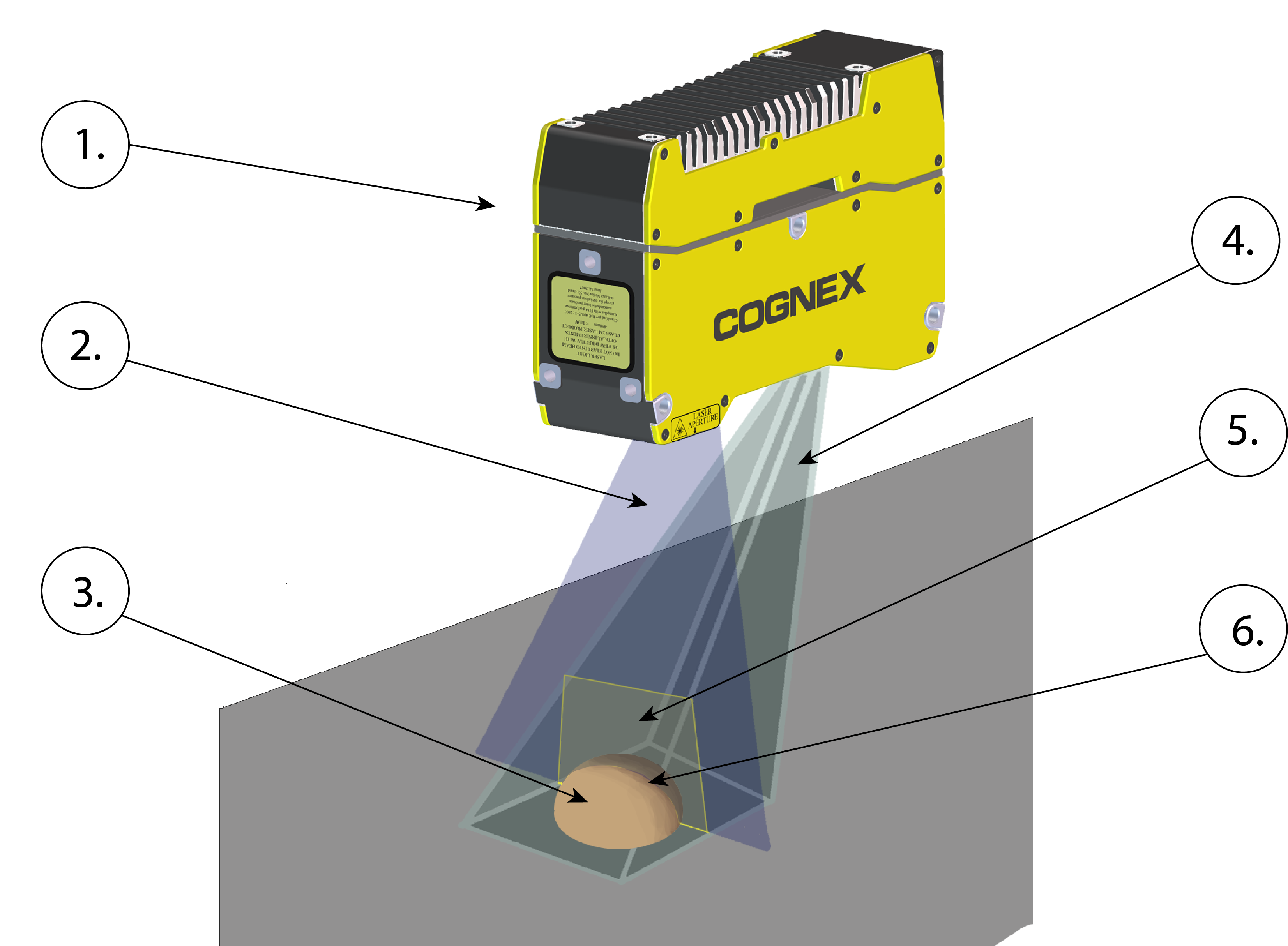
| 1. | In-Sight L38 |
| 2. | Laser plane |
| 3. | Inspected object |
| 4. | Camera field of view |
| 5. | Working section |
| 6. | Laser stripe |
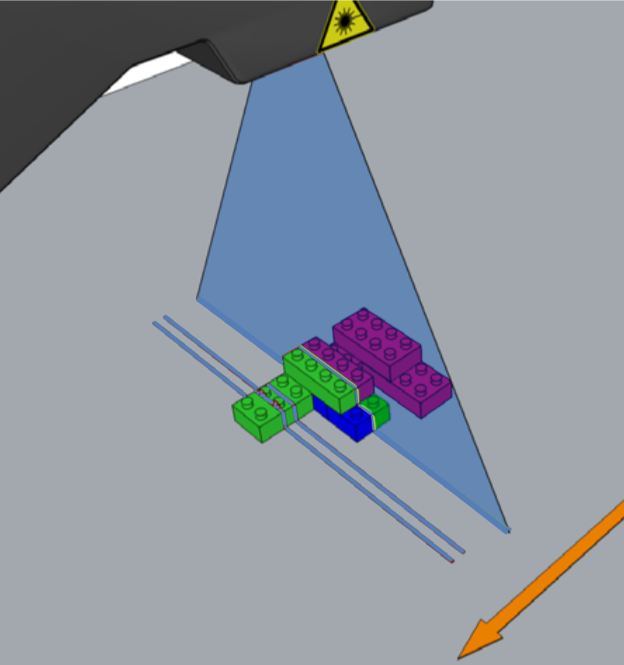
The vision system (1) projects a triangular laser plane (2) onto the object under inspection (3), illuminating the object's surface. The illumination of the laser plane determines the peak data of the raw 2D image and results in the L38's laser stripe (6) within its field of view (4). The surface of the object determines the shape of the laser stripe, which provides the exact height profile information of the object; see the illustration below.
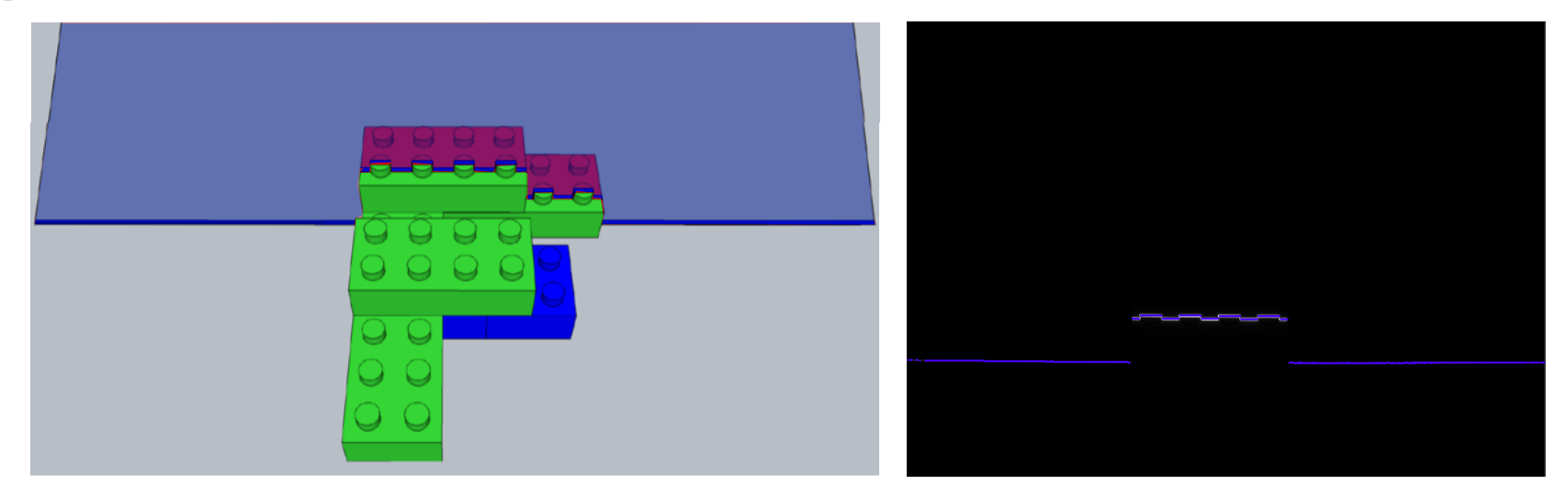
The following image illustrates the laser stripe as seen from the position of the vision system (on the left). The raw 2D image is what the vision system sees (on the right).
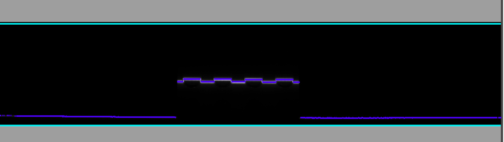
The vision system then applies an algorithm to find the peaks to extract the uncalibrated peak data. On the image below, the CYAN BLUE lines represent a subregion of the field of view working section (see Working Distances and Fields of View), where the vision system is looking for peak data.