Example for Writing User Data
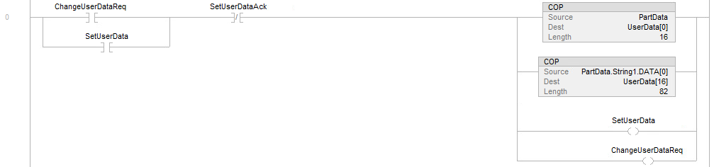
The following image shows an example PLC logic for writing user data, in this case specifically a Rockwell ControlLogix PLC:
The signals used are the following:
| Signal Name | Vision System Defined Signal or Tag | PLC User Defined Tag | Notes |
|---|---|---|---|
| ChangeUserDataReq | - | Yes | Internal memory bit to initiate logic to set the user data. |
| UserData[] | Yes | - | User data byte array holding raw data to write to the vision system. |
| SetUserData | Yes | - | Setting this bit causes the vision system to move the user data from the user data holding buffer to a user data field for the Spreadsheet to use. |
| SetUserDataAck | Yes | - | The vision system sets this bit to acknowledge receiving the SetUserData bit. |
| PartData | - | Yes | This is an internal memory structure PLC tag holding the various parameter tool data settings for tools in the Spreadsheet and gets moved or copied into the UserData byte array. |
When the ChangeUserDataReq bit is set in rung 0, the SetUserDataAck bit is already cleared to 0 which causes the PartData structure elements (booleans, ints, floats, string data) to be copied or moved into the UserData byte array. This mechanism is PLC vendor dependent for copying or moving the data. This sample shows it using a Rockwell ControlLogix PLC. Once the top two branches copy or move the part data to user data the SetUserData output bit is set and the ChangeUserDataReq bit is also held set to 1. When the vision system sets the SetUserDataAck bit to 1 and the PLC reads this, it causes the SetUserData and ChangeUserDataReq bits to be cleared to 0.
The trigger bit could then be set to run the Spreadsheet using the updated tool settings for the inspection.