ReadIDMax

Use the ReadIDMax function to find and decode 1D and 2D symbols. The function supports a variety of symbologies and can handle a high degree of rotation and perspective distortion. Optionally, you can train different 1D and 2D symbologies and check quality metrics.

ReadIDMax returns an IDMax structure which can be referenced with IDMax Vision Data Access Functions.

1D/Stacked Symbologies

The ReadIDMax function supports decoding the following 1D/Stacked symbologies:

  • Code 128

  • Code 39

  • Interleaved 2 of 5

  • UPC/EAN

  • Code 93

  • Codabar

  • MSI

  • Code 25

  • PDF 417

  • DataBar

  • DataBar Limited

  • DataBar Expanded

  • EAN.UCC Composite

Note: 1D/Stacked symbologies do not require any training.

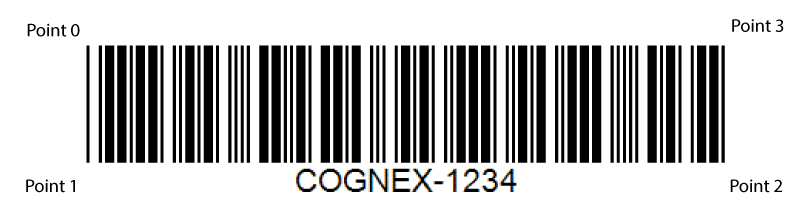
1D Finder Pattern Point

For barcodes, the finder pattern points are centered on each of the four corner cells of the symbol. Point 0 is the cell in the upper-left corner, Point 1 is the lower-left corner, Point 2 is the lower-right corner and Point 3 is the upper-right corner.

2D Symbologies

The ReadIDMax function can locate and decode 2D Data Matrix and QR Code symbols. The function can locate multiple 2D symbols, but unlike 1D symbols, all the symbols must be the same symbology type. For example, if the image contains a mixture of Data Matrix and QR Code symbols, and the Symbology Group parameter of the function is set to Data Matrix, the function ignores the QR Code symbols and only returns the Data Matrix symbols.

You can train the function to decode the same type of 2D symbol by establishing the size of the symbol grid size, the 2D symbology type, and the error checking and correction (ECC) method the symbol uses to verify the accuracy of the data it contains.

Note: Cognex recommends that you train the function when the 2D symbols used in the application all share the same characteristics. If the 2D symbols can vary in grid size or polarity, for example, do not train the function, and allow it to consider all possible settings when decoding a 2D symbol.

Training the ReadIDMax function can improve its performance, especially when all the symbols to be decoded share the same qualities, while not training the function allows it to decode a wider variety of symbols without needing to reconfigure it.

2D Finder Pattern Point:

2D Data Matrix Symbols: For Data Matrix Symbols, the finder pattern points are centered on each of the four corner cells. Also called a module, a cell is a single square, which can be either black or white. For example, a 10 x 10 symbol is made up of 100 black and white cells. One cell is equal to one bit of data of the symbol. The intersection of the two solid lines form the 'L boundary.' During training, the corner of the L should be oriented in the lower-left corner. Point 0 is the cell in the upper-left corner of the symbol, Point 1 is the lower-left corner where the solid lines intersect, Point 2 is the lower-right corner, and Point 3 is the upper-right corner cell.

2D QR Symbols: For QR symbols, the finder pattern points are centered on each of the four corner cells of the symbol. The three position detection patterns on the symbol form an 'L' shape.

During training, the corner of the L must be oriented in the upper-left corner. Point 0 is the cell in the upper-right corner of the symbol, Point 1 is the upper-left corner where the middle position detection pattern forms the corner of the 'L', Point 2 is the lower-left corner, and Point 3 is the lower-right corner cell.

1D/ 2D Image Requirements

The ReadIDMax function requires minimal configuration before scanning 1D symbols, but make sure to follow the following guidelines for input images:

  • All symbols must be greater than 50 pixels in length, while the maximum width of any module cannot exceed 10 pixels.
Note: A module is the narrowest element of the symbol, either a space or a bar.
  • For linear symbologies where modules have different widths, but uniform heights, a module must be at least 1.6 pixels in width and 50 pixels in height.
  • A quiet zone, which is an area on either end of a symbol that contains no marks, must be present that is at least the minimum size specified in the print specification for the symbology type.
  • The contrast between modules and the background must be at least 32 grey levels.
  • The pixel aspect ratio can be no greater than 1.35 to 1.

2D symbols have fewer image requirements. In general, there must be a quiet zone or margin surrounding the symbol on all four sides that is equal to the width of one module inside the symbol itself.

IDMax and IDQuick

The ReadIDMax function offers two processing modes for the decoding algorithm:

  • Choose IDQuick for high-speed decoding of symbols that are well formed and appear in high contrast.
  • Choose IDMax for advanced image processing and image-analysis techniques for challenging images.

By default, the function uses the IDMax mode. However, you can experiment with IDQuick to determine how it affects the performance of the function in the application.

Results

Only symbols that are found and decoded generate results. For each symbol in an image, the ReadIDMax function generates the following results through Vision Data Access Functions:

  • The decoded string.
  • The angular orientation of the found symbol, in degrees.
  • A location (X/Y) for the center of the symbol.
  • The particular symbology of the symbol.
  • Codes and modifiers from the ISO/IEC to uniquely identify the symbology according to industry standards.
Note: The Verify checkbox must be enabled to generate results beyond the decoded string. Use the VerifyIDCode and ValidateIDData functions to process additional verification metrics about the decoded symbol(s).

ReadIDMax Inputs

Note: When configuring the property sheet of the ReadIDMax function, press the OK button to accept the changes and close the property sheet in order to view the effect of updating parameter values. The ReadIDMax function does not support displaying updated results while the property sheet is open.
Parameter Description

Image

This parameter must use Cell References in a spreadsheet cell that contains an Image data structure. By default, this parameter references A0, the cell containing the Image data structure returned by AcquireImage function. This parameter can also reference other Image data structures, such as those returned by the Vision Tool Image Functions.

Fixture

Defines the Region of Interest (ROI) relative to a Fixture input or the output of the image coordinate system for the Vision Tools function. Setting the ROI relative to a Fixture ensures that if the Fixture is rotated or translated, the ROI is rotated or translated in relation to the Fixture.

The default setting is (0,0,0), the top leftmost corner of the image.

X

The X-offset of the origin, in fixture coordinates.

Y

The Y-offset of the origin, in fixture coordinates.

Theta

The rotation from the image X-axis, in the image coordinate system. (+/-360 degrees clockwise)

Region

Also known as the Region of Interest (ROI), specifies the region of the image that undergoes analysis. Double-click on the Region parameter to create an Interactive Graphics Mode that you can transform and rotate. Select this parameter and press the Maximize Region button on the Job Edit toolbar of the property sheet to automatically stretch the region to cover the entire image.

X

The X-offset of the origin, in fixture coordinates.

Y

The Y-offset of the origin, in fixture coordinates.

Height

The dimension along the X-axis of the region.

Note: When reading 1D/Stacked symbols, the ReadIDMax function supports a maximum region size of 2048 pixels in height by 2048 pixels in width. If either the Height or Width parameter is set to a value larger than 2048 pixels, the function returns #ERR.

Width

The dimension along the Y-axis of the region.

Note: When reading 1D/Stacked symbols, the ReadIDMax function supports a maximum size of 2048 pixels in height by 2048 pixels in width. If either the Height or Width parameter is set to a value larger than 2048 pixels, the function returns #ERR.

Angle

The orientation, in fixture coordinates.

Advanced Decode Mode

Specifies the setting to be used to decode Data Matrix or 1D/Stacked symbology groups.

IDMax® (default)

Used for symbols that appear warped, distorted, or appear on a non-uniform background. This mode is designed for codes with "continuous" finder patterns, not separated dots.

IDQuick™

Only reads conformant symbols. It does not attempt to read non-conformant symbols.

Enable Training

When enabled, trains a model of the first symbol read. Training the function can improve performance, especially if all symbols to be decoded have similar characteristics.

If you have multiple symbologies enabled, only the result at index 0 is trained (first result found). For example, if you enable Code 128, Code 39, and UPC/EAN, ReadIDMax trains only Code 128.

The trained information is retained until you clear this check box. To train another symbol, uncheck the checkbox and enable it again. Adding other symbologies to the read does not affect the trained data.

You can train both 1D and 2D codes.

Tip: It is recommended to have only one symbol in the Region when training is enabled.

Off (default)

Do not train a model.

On

Train a model of the first symbol read.

Maximum Results

Specifies the maximum number of symbols to be located and decoded (1 to 128; default = 1).

Note: If the specified value of this parameter exceeds the number of symbols in the ROI, the function still continues to search for the specified number of symbols. If the number of symbols in the ROI varies, you can reduce the execution time of the function by lowering the Timeout parameter.

1D Symbologies

Specifies which 1D symbologies to read. You can select multiple symbologies.

Code 128

Selects Code 128 reading. Code 128 is a very high-density alphanumeric symbology that can be scanned bidirectionally. The symbology can encode the entire 128 ASCII character set plus four non-data characters. A symbol using Code 128 symbology encodes each character using 11 black or white modules, and each symbol includes a checksum character.

Code 39

Selects Code 39 reading. Code 39, also called USS Code 39, BC39, or Code 3 of 9, is a widely-used symbology developed for use in non-retail environments, and can encode both letters, digits, and special characters such as " % " and " / ". A symbol using Code 39 symbology encodes each character using 5 bars and 4 spaces for a total of 9 elements, and 3 out of the 9 elements are always wide. The symbol can include a checksum character for error detection.

Interleaved 2 of 5

Selects Interleaved 2 of 5 reading. Popular in warehouse applications, Interleaved 2 of 5, also called I2of5, I-2/5 or ITF, is a variable-length, numeric-only code. A symbol using Interleaved 2 of 5 symbology encodes 2 characters in a unit of 5 bars and spaces, where the even position character is encoded into bars while the odd position character is encoded into spaces. The Interleaved 2 of 5 symbology can only encode data with an even number length. The symbol can include a checksum character for error detection.

UPC/EAN

Selects UPC (Universal Product Code) and EAN (European Article Numbering) reading. UPC is a fixed-length, numeric-only symbology which can be scanned bidirectionally. The size for a UPC symbol can vary to accommodate various printing processes, but the code works best when the height of the symbol exceeds its width. European companies use the generally equivalent EAN system.

UPC supports Version A (Regular version) and Version E (Zero-suppression version) UPC barcodes, as well as two- and five-character supplemental encodations. EAN supports EAN-8 and EAN-13 barcodes, as well as two- and five-character supplemental encodations.

Code 93

Selects Code 93 reading. Code 93 encodes the same characters as Code 39, but uses nine bar code elements per character instead of 15.

Codabar

Selects Codabar reading, also known as USD-4 and Code 2 of 7. Codabar is an older symbology that encodes digits.

MSI Selects MSI reading. Continous, not self-checking symbology. Used mainly for inventory control.
Code 25 Selects Code 25 reading (also called Code 2 of 5). Code 25 is composed of a single set of varying-width vertical lines (black) and spaces (white). The data in the barcode is represented linearly by these black/white patterns (also called bars/spaces).
PDF 417 Selects PDF 417 reading. PDF 417 is a stacked linear barcode symbol format used in a variety of applications, primarily transport, identification cards, and inventory management.
DataBar Selects DataBar reading (previously referred to as RSS, and also known as GS1 DataBar). DataBar symbols can identify small items and carry more information than the current EAN/UPC bar code.
DataBar Limited Selects DataBar Limited reading (also known as GS1 DataBar Limited).
DataBar Expanded Selects DataBar Expanded reading (also known as GS1 DataBar Expanded).
EAN.UCC
Composite
Selects EAN.UCC Composite reading. When enabled a composite code (a 1D code with a 2D component) can be decoded. The 1D codes that the EAN.UCC can be used with are any of the DataBar family and Code 128
1D Maximum results

Specifies the maximum number of symbols to be located and decoded (1 to 128; default = 1).

Note: If the specified value of this parameter exceeds the number of symbols in the ROI, the function still continues to search for the specified number of symbols. If the number of symbols in the ROI varies, you can reduce the execution time of the function by lowering the Timeout parameter.

Stacked Symbologies

Specifies which Stacked Symbologies to read. You can select multiple symbologies. The below options are only available when the Symbology Group parameter is set to 1D/Stacked.

PDF 417

Selects PDF 417 reading. PDF 417 is a stacked linear barcode symbol format used in a variety of applications, primarily transport, identification cards, and inventory management.

DataBar

Selects DataBar reading, previously referred to as RSS, and also known as GS1 DataBar. DataBar symbols can identify small items and carry more information than the current EAN/UPC bar code.

DataBar Limited

Selects DataBar Limited reading, also known as GS1 DataBar Limited.

DataBar Expanded

Selects DataBar Expanded reading, also known as GS1 DataBar Expanded.

EAN.UCC
Composite

Selects EAN.UCC Composite reading. When enabled, a composite code, which is a 1D code with a 2D component, can be decoded. You can use EAN.UCC wih the 1D codes DataBar and Code 128.

Decode Settings

Settings that are not applicable to the symbology types you selected are greyed out.

Perspective Distortion

Specifies the decoding of Data Matrix and QR Code symbols with perspective distortion and optionally trains Data Matrix symbols for a known perspective distortion.

No perspective

(default)

Decodes Data Matrix symbols that have no perspective distortion.

Perspective

Decodes Data Matrix, QR Code and 1D/Stacked symbols with perspective distortion. The perspective distortion is estimated independently during model training and run time.

Train perspective

Decodes Data Matrix symbols with a known perspective distortion. The perspective is trained, then at run time, the function searches for the symbol in a space where the perspective distortion in the input image is compensated using the trained attributes. This option requires that the run time symbol is placed on the same plane as that of the trained symbol. This option provides the ability to decode severely damaged symbols with known perspective distortion.

Note: Make sure that the vision system is mounted such that the angle of incidence, which is the angle between the optical axis of the sensor and the normal vector of the plane on which the symbol is presented, is no more than 40 degrees, and the resolution of the symbol is at least 5 pixels per cell.

QR Mode

Specifies the type of QR Code to read.

  • QR Model 1

  • QR Model 2

  • QR Models 1 and 2

  • Micro QR

  • Micro QR and QR Model 1

  • Micro QR and QR Model 2

  • All QR Modes (default)

Ignore Polarity

Specifies whether or not to read Data Matrix symbols where the polarity is inverted, with respect to the trained symbol.

Note: This parameter is only valid if the Enable Training parameter is On.

Off (default)

Do not allow inverted polarity from the trained model.

On

Allow inverted polarity from the trained model.

Allow Flexible
Grid Size

Specifies whether or not to read Data Matrix and QR Code symbols of a different grid size with respect to the trained symbol.

Note: This parameter is only valid if the Enable Training parameter is On.

Off (default)

Only allow symbols to be read that are the same grid size as the trained symbol.

On

Allow symbols to be read that are not the same grid size as the trained symbol.

Checksum

Determines if the symbol is valid to ensure reliability using an error-detection algorithm. Checksum only applies to symbols with optional checksum algorithms included in the symbol; each symbol has its own unique checksum algorithm. The type of checksum, if any, that is used depends on the code type selected.

OFF (default)

Do not verify checksum.

ON

Requires checksum to pass.

Note: Code 128, Code 93, and UPC/EAN barcodes are validated with a checksum regardless of the parameter selection. If Checksum is enabled for any other barcode, and no checksum is encoded, the read fails.

Polarity

Specifies the color of the symbols.

Black

The symbol is darker than the background.

White

The symbol is lighter than the background.

Auto (default)

The function automatically selects the polarity of the symbol.

Omnidirectional

Specifies the direction in which scan lines are projected within the Region in order to detect all of the elements in the barcode. At least one scan line must project across every element of the barcode for a successful decode.

0 = OFF

Scan lines are projected in one direction to detect a barcode parallel to the Region.

1 = ON (default)

Scan lines are projected at various angles to detect a barcode that is rotated relative to the Region.

Sort Mode

Specifies the order, if any, in which results are returned.

Note: For accurate sorting of symbols, the Maximum Results parameter must be set to a value that is equal to or greater than the number of symbols contained in the image.

None (default)

Sorts by first decoded results. The undecoded results follow the decoded results.

Top Down

Sorts in ascending Row order.

Left To Right

Sorts in ascending Column order

Alphabetical

Sorts the results alphabetically.

String Length

Sorts the results by string length (shortest to longest).

Rows

Sorts the results by grouping the symbols into rows, and then sorting them from left-to-right within each row. When sorting by Rows, two symbols are considered part of the same Row if the center of one symbol overlaps vertically with any part of the other symbol.

Columns

Sorts the results by grouping the symbols into columns, and then sorting them from top-to-bottom within each column. When sorting by Columns, two symbols are considered part of the same Column if the center of one overlaps horizontally with any part of the other symbol.

Allow Identical 1D Symbols

Specifies whether or not the function has to decode all symbols within the region, even if they are identical. Two symbols are considered identical if they have the same length, symbology type and decoded string.

OFF (default)

Only return one result if multiple symbols are decoded.

ON

Return all results, even if they are identical.

Expand UPC-E

Specifies whether the decoded symbol returns the 6-digit UPC-E string or the expanded 11-digit UPC-A equivalent string.

OFF

The decoded symbol returns the 6-digit UPC-E string.

ON (default)

The decoded symbol returns the expanded 11-digit UPC-A equivalent string.

Verify

Specifies whether the print quality tests (also known as quality verification metrics) are performed.

OFF (default)

Do not test quality.

ON

Test quality and display the results in the spreadsheet.

Note:
  • If the string cannot be decoded, then #ERR is returned for all results that are automatically inserted into the spreadsheet.
  • All Code Types support quality verification metrics, except for the following code types:
    • PDF 417
    • MaxiCode
    • Aztec Code
    • DotCode

Timeout

Specifies the amount of time, in milliseconds (0 to 30000), that the function searches for a valid ID symbol before execution stalls and an #ERR is returned. Setting the value to 0 disables the setting and a timeout is not applied.

Note: At times, the ReadIDMax function can exceed the specified Timeout parameter value by varying percentages. If this happens, decrease the Timeout parameter value to compensate for the overage.

Show

Specifies the display mode for the ReadIDMax graphical overlay on the image.

Note: The Show parameter is only implemented for Data Matrix and QR Code symbols.

Hide All (default)

The input region boundary is hidden, except when the cell containing the ReadIDMax function is highlighted in the spreadsheet.

Result Graphics Only

The result graphics (boxes for Data Matrix and QR Code) are displayed at all times.

Input and Result Graphics

The input graphics and result graphics are displayed at all times.

ReadIDMax Outputs

Returns

An IDMax data structure containing the decoded alphanumeric string, or #ERR if any of the input parameters are invalid.

Results

When the function is initially inserted into a cell, a result table is automatically inserted into the spreadsheet. The number of indexed strings returned in the result table is equal to the value entered in the Maximum Results parameter. If no symbol can be located and decoded, then #ERR is returned.

Note: For Data Matrix symbols, the base 256 latch character (Decimal 231 Hex E7) causes encoded data to be processed as bytes, per the Data MatrixISO/IEC 16022 specification. Use the GetStringIDMax function to return the encoded data. For more information, see IDMax.

IDMax Vision Data Access Functions

If the Verify checkbox is disabled when the ReadIDMax function is initially created, then a single Vision Data Access function is automatically inserted into the spreadsheet:

String GetString(IDMax, [Index]) Returns the alphanumeric string encoded in the indexed symbol.

If the Verify checkbox is enabled and the function performs additional quality verification metrics when the ReadIDMax function is initially created, the additional Vision Data Access Functions that are automatically inserted into the Spreadsheet depend on the selected Symbology Group. You can access additional data elements using the ReadIDMax Vision Data Access Functions. For more information, see IDMax.

Note:
  • If the Verify checkbox is enabled after the ReadIDMax function is initially created, the additional Vision Data Access Functions are not automatically inserted into the spreadsheet. Also, the Verify checkbox must be enabled before the additional Vision Data Access Functions executes in the spreadsheet.
  • If decoding Data Matrix symbols, use the GetStringIDMax function instead of GetString for more accurate and detailed information about the decoded symbol.