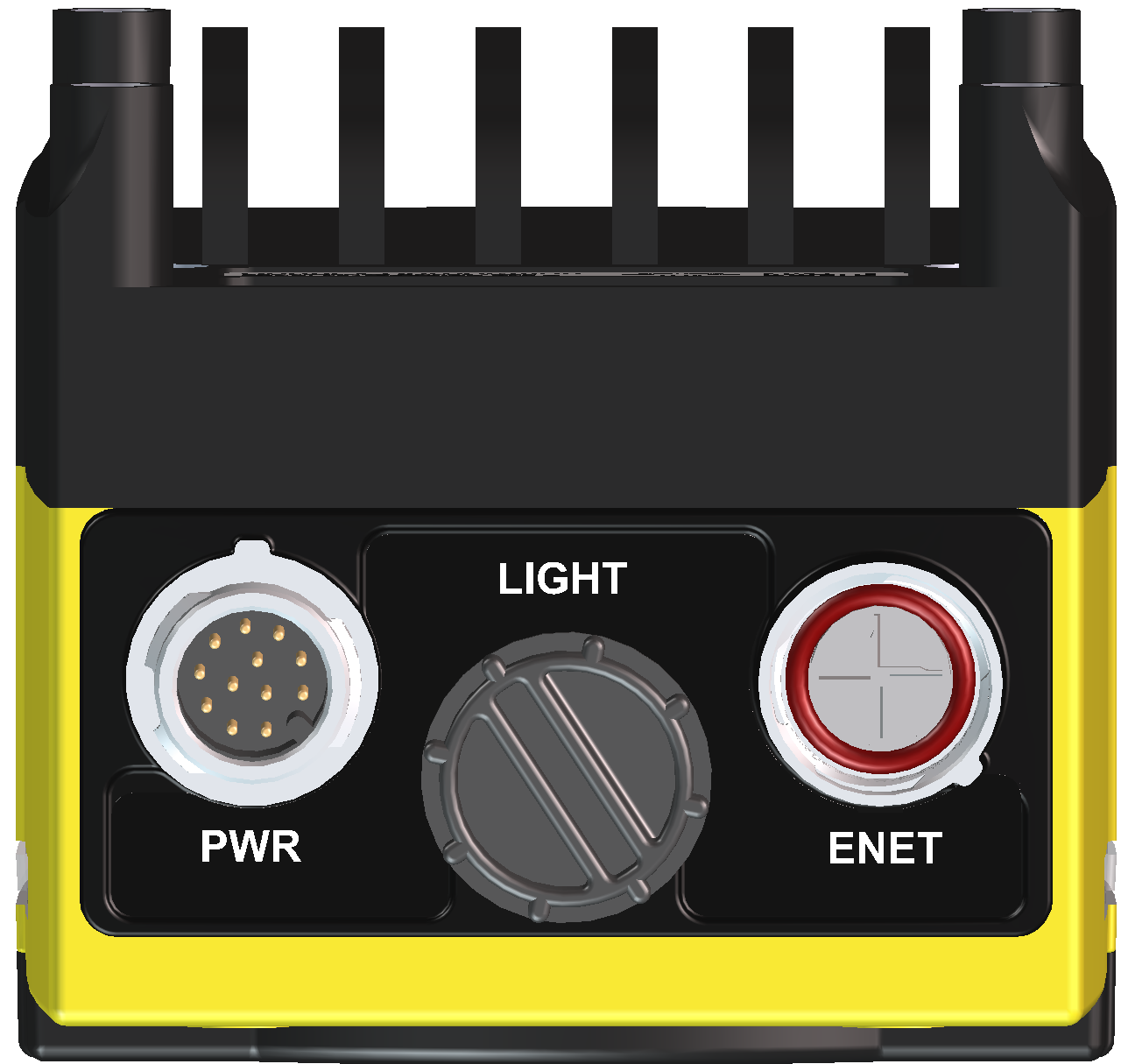
Connectors and Indicators
|
|
|---|---|
| Connector | Function |
| PWR Connector |
Connects the Breakout cable, which provides connections to an external power supply, the acquisition trigger input, general-purpose inputs and high-speed outputs. For more information, refer to Breakout Cable. |
| LIGHT Connector |
Connects the vision system to an external lighting device. For more information, refer to External Light Connector. |
| ENET Connector |
Connects the Ethernet cable, which provides 10/100/1000 Ethernet connectivity. For more information, refer to Ethernet Cable. |
|
||
|---|---|---|
| Indicator | Function | |
|
|
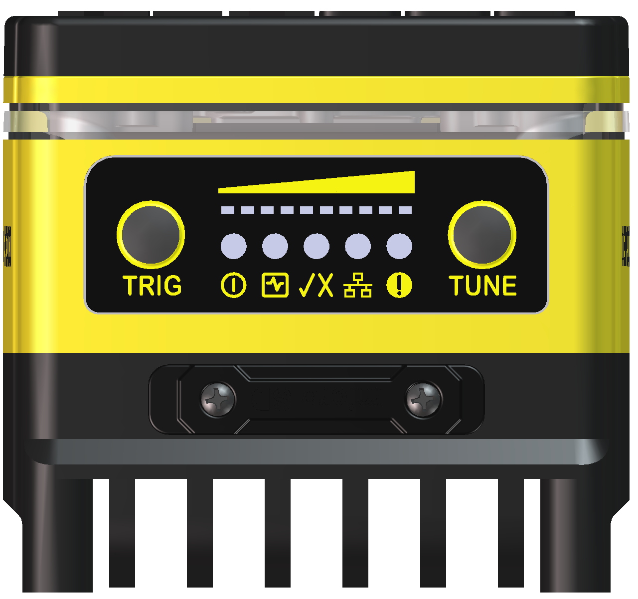
Focus Metric LEDs |
Not supported. |
|
|
TRIG Button |
Not supported. |
|
|
Power LED | The green LED illuminates to indicate that the vision system is powered on. |
|
|
SD Card Status LED |
|
|
|
Pass/Fail LED and Indicator Ring | Green or red when active. User configurable. |
|
|
Network LED | The yellow LED flashes to indicate network activity. |
|
|
Error LED | Red when active. User configurable. |
|
|
TUNE Button |
Not supported. |