 Integrating In-Sight Vision Systems into RSLogix 5000 v20
This topic covers integrating In-Sight vision systems running In-Sight 5.2.0 or later firmware, in RSLogix 5000, version 20 and beyond. These versions of RSLogix 5000 support EDS files. In-Sight Explorer includes .L5X files, which places tag data in user-friendly program tags, representing signals in the vision sensor running In-Sight 5.2.x or later firmware. InSight_11_CopyRung.L5X file will be used for sensors running the 5.X firmware.
-
Create and add an EDS module in RSlogix5000
- EDS files are installed with Insight Explorer software at the following location: C:\Program Files (x86)\Cognex\In-Sight\In-Sight Explorer 5.2.3\Factory Protocol Description\EDS
- From the Tools drop down menu in RSLogix5000, run the EDS installation tool to install the EDS file for the In-Sight 2000.
- From the IO Configuration section of RSLogix5000, right-click on the network node and select New Module from the menu.
-
From the Select Module dialog, open the Communications node and select the In-Sight 2000-xxx from the list and click OK.
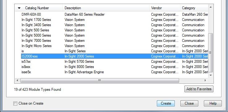
The dialog will be replaced with a New Module configuration dialog.
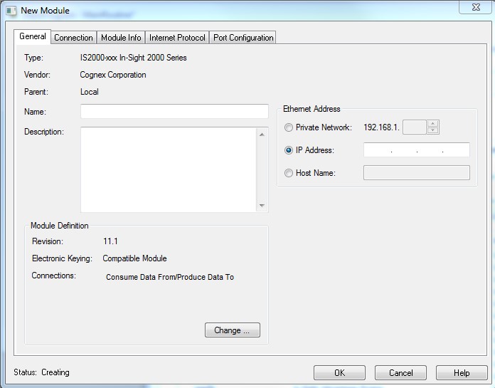
Enter the name of the vision sensor, its IP address and its connection parameters as shown above. If there are multiple vision sensors, each should have a unique name. For this example, there is only one vision sensor to configure.
Tip: Refer to the In-Sight Explorer help files for the EtherNet/IP Object Model (Input and Output Assembly bits) that correspond to the version of firmware running on the vision sensor.
-
Import Rung
-
Access the Main Routine which can be found in the Tasks > Main Task > Main Program folder in the Controller Organizer pane. If this is a new ladder program, the empty rung zero can be used. If the vision sensor will be integrated into an existing program, it is recommended to add a rung at the top of the ladder to ensure updated data is read from and written to the sensor’s input and output assemblies prior to the rest of the ladder executing.
-
Once there is an empty rung at the top of the ladder program, right-click on that rung and select Import Rung from the menu.
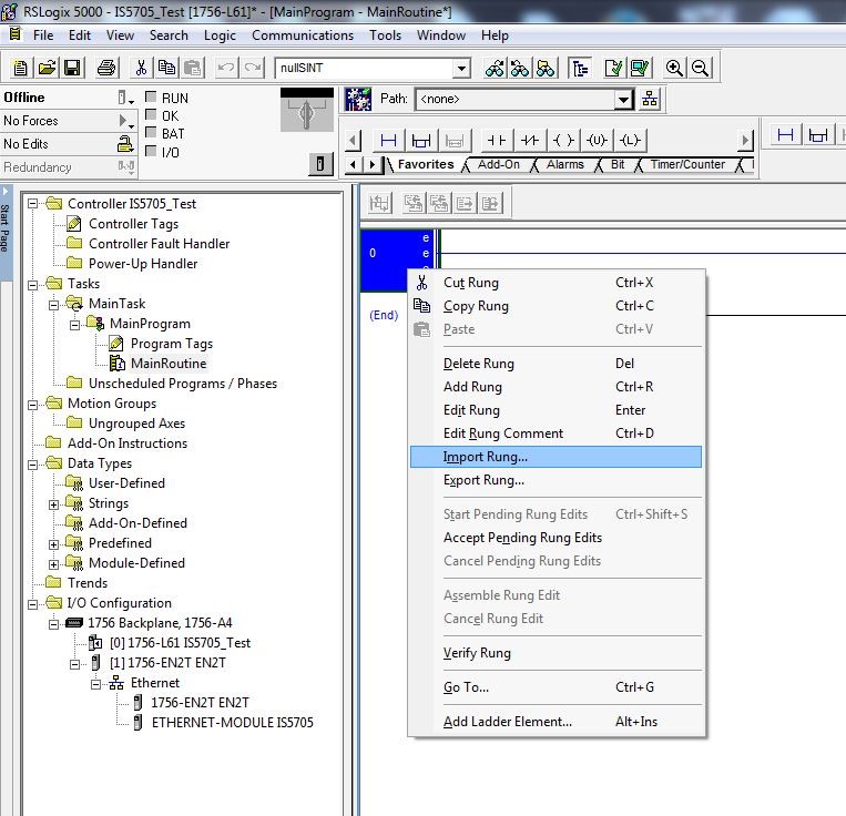
-
Use the Import Rung dialog to browse to the folder location containing this document and the two import rung files. Since the Insight 2000 uses a 5.X firmware, the InSight_11_CopyRung.L5X file will be used.
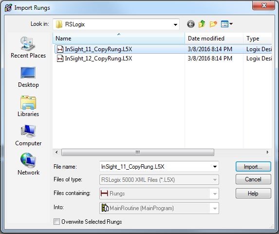
-
Once the appropriate file has been selected, click the Import button.
-
The Import Configuration dialog will appear with generic names to be used for tag generation.
-
-
Renaming of tags: The generic module will create a single array of raw unstructured data for both the input to/from the module. For this example – the generic module created In-Sight 2000:I, In-Sight 2000:0, and In-Sight 2000:C (which is not used). The Input assembly will be one contiguous array consisting of the Status block and the Inspection Results array, and the Output assembly will be a contiguous array consisting of the Control Block and the User Data array, both without any identifying tags. Once the project is downloaded to the PLC and the rung with the copy instructions is executed for the first time, two new arrays containing the tags will be created (and identical to the tags you would see if an Add-on-profile module were available).
-
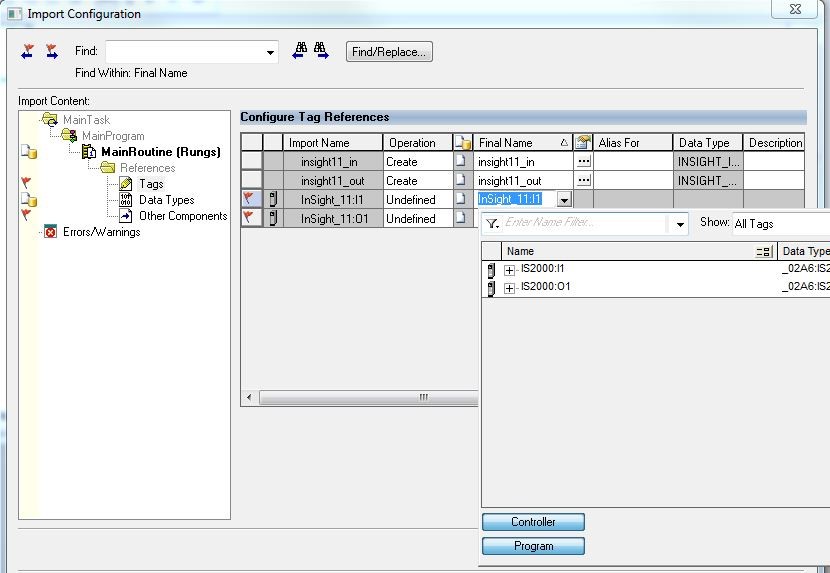
The bottom two lines with flag to the left of them will need to be edited by clicking in the white space of the Name field. These tags contain the raw unstructured data of the I/O assemblies on In-Sight. A down arrow will appear after clicking the space.
-
Clicking the arrow will produce a drop down menu with replacement options for the default name. In this list there will be names that match the name of the generic module. In this example, the generic module was named In-Sight 2000, so “In-Sight 2000:I” and an “In-Sight 2000:O” will appear in the list. Replace both lines with the corresponding name that matches the name of the generic module. Note that In-Sight 2000:C is not used.
-
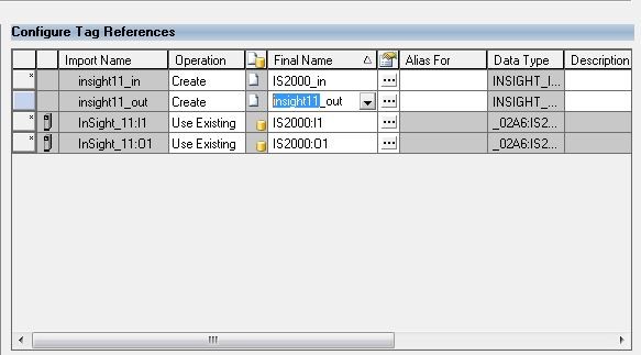
Next, edit the top two lines in the Import Configuration. Click on the text of the name so the cursor appears. It is best practice to replace everything before the “_In” and “_Out” with the name of generic module, or some other easily identifiable name. Since this example only uses one vision sensor, the name “In-Sight 2000” was used.
-
Now that all of the default tag names have been changed, it is necessary to specify where the tags will be created. Skipping this step will place the new tags in the Program Tag table just above the Main Routine.
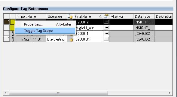
To put the tags in the Controller Tag table—as an AOP would do, were it available—right-click in the empty box next to each of the Import Names where the controller card icon is missing. These spaces have been highlighted in the capture below. Right clicking in this space will produce a drop down menu where Toggle Tag Scope can be selected. This will place the controller card icon in the previously empty box.
-
After all the names have been changed from their default values, click the OK button.
Note: The names, In-Sight 2000_In and In-Sight 2000_Out, can be any names, so long as it is unique to each vision sensor added to the IO configuration. If multiple sensors are being deployed, these steps must be followed for each sensor, as each instance of the copy rungs that get created will point to a specific sensor. Care should be taken when choosing names to make any future trouble shooting easier and to avoid confusion. For example, if more than one sensor is present, the names could be “Line_One_In-Sight 2000_In” and “Line_One_In-Sight 2000_Out". -
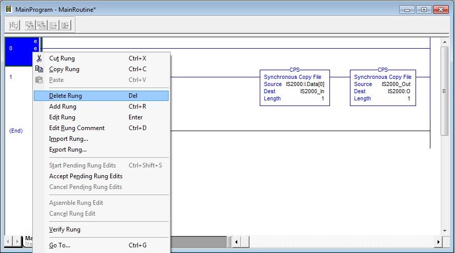
A new, empty rung will be added to the Main Routine. This rung can be deleted.
-
-
Downloaded to the PLC
-
Download the project to the PLC.
-
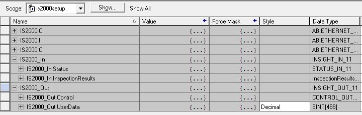
Put the PLC into Run Mode. After the rungs holding the copy instructions haven been run, the new tags will be created in the Program Tags table (the same as would occur with the Add on Profile, were it to exist).
In this example, the In-Sight 2000:I & In-Sight 2000:O are the raw input and output assemblies from the vision sensor, and the MyCamera_In and MyCamera_Out will contain the Control and Status blocks as well as the UserData and InspectionResults arrays as shown in the following table:
-