Robot Communications - ABB Robot Controller
Overview
The purpose of this topic is to outline the steps to connect and transfer data from an In-Sight vision system to a ABB Robot Controller.For this topic, the robot controller will be the device controlling the acquisition and transfer of data.In general, the robot controller, with the use of In-Sight Native Mode commands, will trigger the vision system to acquire and process an image and then the robot controller will request specific data from the vision system.Data can be transferred using serial or Ethernet communications. For more information, see Native Mode Commands.
Required Hardware
- In-Sight vision system (In-Sight Micro 1000 series, In-Sight 5000 series, In-Sight 7000 series or the In-Sight 8000 series vision system)
-
For serial communications, an I/O module, Breakout cable (In-Sight 5000 series or In-Sight 7000 series only).
Note:- While serial-based robot communications are supported with the Breakout cable (In-Sight 5000 series or In-Sight 7000 series only), an I/O module is recommended for ease of setup.
- In-Sight Micro 1000 series vision systems only support serial communication when connected to the CIO-MICRO or CIO-MICRO-CC I/O module.
- There are two options for enabling serial communication for the In-Sight 70xx - 74xx series vision system: using the Breakout cable or using the CIO-MICRO or CIO-MICRO-CC I/O module. When connected to the Breakout cable (and there is no connection to an I/O module), the vision system allows one discrete input line and one discrete output line to be configured as Serial Receive and Serial Transmit, respectively.
- In-Sight 8000 series vision systems only support serial communication when connected to the CIO-MICRO I/O module.
- The CIO-WENET Ethernet I/O module does not support serial communication.
- DB9 Serial Cable or Ethernet Cable
- Computer
- ABB Robot Controller (IRC5, S4Cplus or S4P+)
- PC Interface (Recommended for Ethernet communications but not required)
- Vision System Interface (for Serial communications)
Required Software
- Cognex In-Sight Explorer version 3.3.0 or higher
- Cognex In-Sight firmware version 3.3.0 or higher
- ABB RAPID programming language
Serial Communications
Robot Controller RAPID code
MODULE VISION! DATA DECLARATIONSPERS num nXOffs:=0;PERS num nYOffs:=0;PERS num nAngle:=0;VAR string stReceived;VAR iodev ComChannel;PERS tooldata tGripper:=[TRUE,[0,0,0],[0,0,0,1]],[5,[0,0,],[1,0,0,0],0,0,0]];PERS tooldata tVision:=[TRUE,[[0,0,0],[0,0,0,1]],[5,[0, 0, 0],[1,0,0,0],0,0,0]];CONST robtarget pHome:=[[0,0,0],[0,0,0,1],[-2,0,1,0],[9E+09,9E+09,9E+09,9E+09,9E+09,9E+09]];CONST robtarget pVisionPos:=[[0,0,0],[0,0,0,1],[-2,0,-1,0],[9E+09,9E+09,9E+09,9E+09,9E+09,9E+09]];PROC Main()MoveL pHome,v1000,fine,tVision;GetVisionData;MoveL Reltool(pVisionPos,nXOffs,nYOffs,0\Rz:=nAngle),v500,fine,tGripper;WaitTime 3;MoveL pHome,v1000,fine,tVision;ENDPROCPROC GetVisionData()VAR string XData:="";VAR string YData:="";VAR string AngleData:="";VAR num NumCharacters:=9;VAR bool bOK;nXOffs:=0;nYOffs:=0;nAngle:=0;Close ComChannel;Open "COM2", ComChannel \Append\Bin;ClearIOBuff ComChannel;WaitTime\InPos, 0.5;! Instruction In-Sight to Acquire an Image! and not return until completeWriteStrBin ComChannel, "sw8\0D";CheckStatus;! Get the value in cell C7WriteStrBin ComChannel, "gvc007\0D";CheckStatus;! Read the X-offsetXData:= ReadStrbin (ComChannel, NumCharacters \Time:=5);! Read the Y-offsetYData:= ReadStrbin (ComChannel, NumCharacters \Time:=5);! Read the Angle-offsetAngleData:= ReadStrbin (ComChannel, NumCharacters \Time:=5);!Closes Serial Channel "COM2"Close ComChannel;!Convert String Data To Numerical DatabOK:=StrToVal(XData,nXOffs);bOK:=StrToVal(YData,nYOffs);bOK:=StrToVal(AngleData,nAngle);ENDPROCPROC CheckStatus()stReceived:=ReadStrBin(ComChannel,1\Time:=5);IF stReceived<>"1" THENTPErase;TPWrite "Vision Error!";Stop;ENDIFClearIOBuff ComChannel;ENDPROCENDMODULE
In-Sight Serial Port Setup
While connected to the vision system (with the vision system Offline):
- On the Sensor menu, click Serial Port Settings.
-
Click the I/O Module button to open the I/O Module Configuration dialog and configure the I/O module. Press the OK button to close the I/O Module Configuration dialog and return to the Serial Port Settings dialog.
Note: If the vision system is configured for use with the CIO-MICRO or CIO-MICRO-CC I/O module, the RS-232 TRANSMIT and RS-232 RECEIVE pins on the Breakout cable are disabled. Use the I/O module's RS-232 OUT port (DB9) to connect to a serial device. -
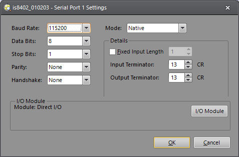
Set the following properties in the Serial Port Settings dialog:
- Baud Rate: 115200
- Data Bits: 8 (set by default when using the CIO-1400)
- Stop Bits: 1 (set by default when using the CIO-1400)
- Parity: None
- Handshake: None
- Mode: Native
- Fixed Input Length: Disabled
- Input Terminator: 13
- Output Terminator: 13
- Verify that the dialog displays the "(attached)" message next to the I/O modulethat is physically attached to the vision system.
- Click OK.
In-Sight Job Setup
- From the File menu, create a New Job.
- In the AcquireImage property sheet (double-click on cell A0), set the following parameters:
- Trigger = External
- Manual = Checked
- Select cell A2 and type ExtractBlobs and press Enter (at this point the ExtractBlobs property sheet will be displayed).
- Click OK (leaving all parameters at their default settings).
- Select cell A4 and, from the Palette's Snippets tab, insert the Communication > Robots > ABB.cxd Snippet into the spreadsheet.
- Define the coordinate cell references:
- X: Double-click C6, double-click C2,
- Y: Double-click D6, double-click D2
- Angle: Double-click E6, double-click E2
- Press the Manual Trigger icon a few times to confirm that data from the ExtractBlobs function is changing.
- Save the job.
- Put the vision system Online.
Ethernet Communications
Robot Controller Setup
The code example shows the controller connecting to an In-Sight vision system with the IP address 192.168.0.1; To find the IP address of your vision system, from In-Sight Explorer, right-click the vision system name in the In-Sight Network tree and select Properties.
Robot Controller RAPID code
MODULE VISION! DATA DECLARATIONSPERS num nXOffs:=0;PERS num nYOffs:=0;PERS num nAngle:=0;VAR string stReceived;VAR socketdev ComSocket;PERS tooldata tGripper:=[TRUE,[0,0,0],[0,0,0,1]],[5,[0,0,],[1,0,0,0],0,0,0]];PERS tooldata tVision:=[TRUE,[[0,0,0],[0,0,0,1]],[5,[0, 0, 0],[1,0,0,0],0,0,0]];CONST robtarget pHome:=[[0,0,0],[0,0,0,1],[-2,0,1,0],[9E+09,9E+09,9E+09,9E+09,9E+09,9E+09]];CONST robtarget pVisionPos:=[[0,0,0],[0,0,0,1],[-2,0,-1,0],[9E+09,9E+09,9E+09,9E+09,9E+09,9E+09]];PROC Main()ConnectToInSight ;MoveL pHome,v1000,fine,tVision;GetVisionData;MoveL Reltool(pVisionPos,nXOffs,nYOffs,0\Rz:=nAngle),v500,fine,tGripper;WaitTime 3;MoveL pHome,v1000,fine,tVision;GetVisionData;MoveL Reltool(pVisionPos,nXOffs,nYOffs,0\Rz:=nAngle),v500,fine,tGripper;WaitTime 3;MoveL pHome,v1000,fine,tVision;SocketClose ComSocket;ENDPROCPROC GetVisionData()VAR string XData:="";VAR string YData:="";VAR string AngleData:="";VAR num NumCharacters:=9;VAR bool bOK;nXOffs:=0;nYOffs:=0;nAngle:=0;status := SocketGetStatus(ComSocket);IF status <> SOCKET_CONNECTED THENTPErase;TPWrite "Vision Sensor Not Connected";Return;ENDIF! Instruct In-Sight to Acquire an Image! and not return until completeSocketSend ComSocket \Str:="sw8\0d\0a";CheckStatus;SocketReceive ComSocket \Str:=stReceived;! Get the value in cell C7SocketSend ComSocket \Str:="gvc007\0d\0a";! Read the dataSocketReceive ComSocket \Str:=stReceived;! Parse the data stringXData:= StrPart(stReceived, 3, NumCharacters);YData:= StrPart(stReceived, NumCharacters, NumCharacters);AngleData:= StrPart(stReceived, 2*NumCharacters, NumCharacters);!Convert String Data To Numerical DatabOK:=StrToVal(XData,nXOffs);bOK:=StrToVal(YData,nYOffs);bOK:=StrToVal(AngleData,nAngle);SocketClose ComSocket;ENDPROCPROC CheckStatus()SocketReceive ComSocket \Str:=stReceived;IF stReceived <> "1\0d\0a" THENTPErase;TPWrite "Vision Error!";Stop;ENDIFENDPROCPROC ConnectToInSight()var num found:=0;var num length:=0;SocketCreate ComSocket;SocketConnect ComSocket, "192.168.0.1", 23;SocketReceive ComSocket \Str:=stReceived;Length:=strlen(stReceived);found:=strmatch(stReceived,1,"User:");IF found = length+1 THENTPErase;TPWrite "Vision Login Error (User Prompt)";Stop;ENDIF! Send the UsernameSocketSend ComSocket \Str:="admin\0d\0a";SocketReceive ComSocket \Str:=stReceived;IF stReceived <> "Password: " THENTPErase;TPWrite "Vision Login Error (Password Prompt)";Stop;ENDIF! Send PasswordSocketSend ComSocket \Str:="\0d\0a";SocketReceive ComSocket \Str:=stReceived;IF stReceived <> "User Logged In\0d\0a" THENTPErase;TPWrite "Vision Login Error (Final Login)";Stop;ENDIFENDPROCENDMODULE
In-Sight Job Setup
- From the File menu, create a New Job.
- In the AcquireImage property sheet (double-click on cell A0), set the following parameters:
- Trigger = External
- Manual = Checked
- Select cell A2 and type ExtractBlobs and press Enter (at this point the ExtractBlobs property sheet will be displayed).
- Click OK (leaving all parameters at their default settings).
- Select cell A4 and, from the Palette's Snippets tab, insert the Communication > Robots > ABB.cxd Snippet into the spreadsheet.
- Define the coordinate cell references:
- X: Double-click C6, double-click C2,
- Y: Double-click D6, double-click D2
- Angle: Double-click E6, double-click E2
- Press the Manual Trigger icon a few times to confirm that data from the ExtractBlobs function is changing.
- Save the job.
- Put the vision system Online.
Troubleshooting
Serial with HyperTerminal
In-Sight Serial Port Setup
While connected to the vision system (with the vision system Offline):
-
On the Sensor menu, click Serial Port Settings.
-
Click the I/O Module button to open the I/O Module Configuration dialog and configure the I/O module. Press the OK button to close the I/O Module Configuration dialog and return to the Serial Port Settings dialog.
Note: If the vision system is configured for use with the CIO-MICRO or CIO-MICRO-CC I/O module, the RS-232 TRANSMIT and RS-232 RECEIVE pins on the Breakout cable are disabled. Use the I/O module's RS-232 OUT port (DB9) to connect to a serial device. -
Set the following properties in the Serial Port Settings dialog:
- Baud Rate: 115200
- Data Bits: 8 (set by default when using the CIO-1400)
- Stop Bits: 1 (set by default when using the CIO-1400)
- Parity: None
- Handshake: None
- Mode: Native
- Fixed Input Length: Disabled
- Input Terminator: 13
- Output Terminator: 13
- Verify that the dialog displays the "(attached)" message next to the I/O module that is physically attached to the vision system.
- Click OK.
Set Up a Test Job
- From the File menu, create a New Job.
- In the AcquireImage property sheet (double-click on cell A0), set the following parameters:
- Trigger = External
- Manual = Checked
- Select cell A2 and type ExtractBlobs and press Enter (at this point the ExtractBlobs property sheet will be displayed).
- Click OK (leaving all parameters at their default settings).
- Select cell A4 and type FindBlobs and press Enter (at this point the FindBlobs property sheet will be displayed).
- Reference cell B2 for the Blobs parameter.
- Click OK.
- Press the Manual Trigger icon a few times to confirm that data is changing.
- Put the vision system Online.
Connect to an In-Sight Vision System
- From Windows, click Start > All Programs > Accessories > Communications > HyperTerminal.
- Create a New Connection (File > New Connection).
- Port: COM1
- Bits per second: 115200
- Data bits: 8
- Parity: None
- Stop bits: 1
- Flow Control: None
- Click File > Properties > Settings.
- Emulation: ANSI
- ANSII Setup (for viewing ease) set the following:
- Send line ends with line feeds
- Echo typed characters locally
- Append line feeds to incoming line ends
- Wrap lines that exceed terminal width
- Click Connect.
- Enter the vision system's user name then password (default user name is admin and the password in blank).
- You should now see "User Logged In".
- Type: SW8 and press Enter (this will cause a manual trigger and the image should change).
- Type: GVC004 and press Enter (this will get the value stored in cell C4).
Verify Ethernet Connection with Telnet
Set Up a Test Job
- From the File menu, create a New Job.
- In the AcquireImage property sheet (double-click on cell A0), set the following parameters:
- Trigger = External
- Manual = Checked
- Select cell A2 and type ExtractBlobs and press Enter (at this point the ExtractBlobs property sheet will be displayed).
- Click OK (leaving all parameters at their default settings).
- Select cell A4 and type FindBlobs and press Enter (at this point the FindBlobs property sheet will be displayed).
- Reference cell B2 for the Blobs parameter.
- Click OK.
- Press the Manual Trigger icon a few times to confirm that data is changing.
- Put the vision system Online.
Connect to an In-Sight Vision System
- From Windows, click Start > Run...
- In the Run window type: telnet <sensor's IP Address> (example: telnet 10.27.80.66).
- Click OK.
- Enter the vision system's user name then password (default user name is admin and the password in blank).
- You should now see "User Logged In".
- Type: SW8 and press Enter (this will cause a manual trigger and the image should change).
- Type: GVC004 and press Enter (this will get the value stored in cell C4).
- To disconnect your telnet session type CTRL + ].
- Type "quit" to close the window.