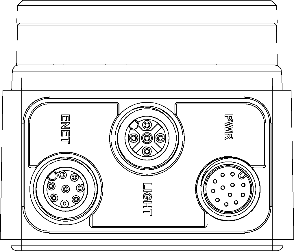
Connectors and Indicators
|
|
|---|---|
| Connector | Function |
| ENET Connector | Connects the vision system to a network. The ENET connector provides the Ethernet connection to external network devices. For more information, refer to the Ethernet Cable Specifications. |
| LIGHT Connector | Connects the vision system to an external lighting device. For more information, refer to the Light Cable Specifications. |
| PWR Connector | Connects the Breakout cable, which provides connections to an external power supply, the acquisition trigger input, general-purpose inputs, high-speed outputs, and RS-232 serial communications. For more information, refer to the Breakout Cable Specifications. |
|
|
|---|---|
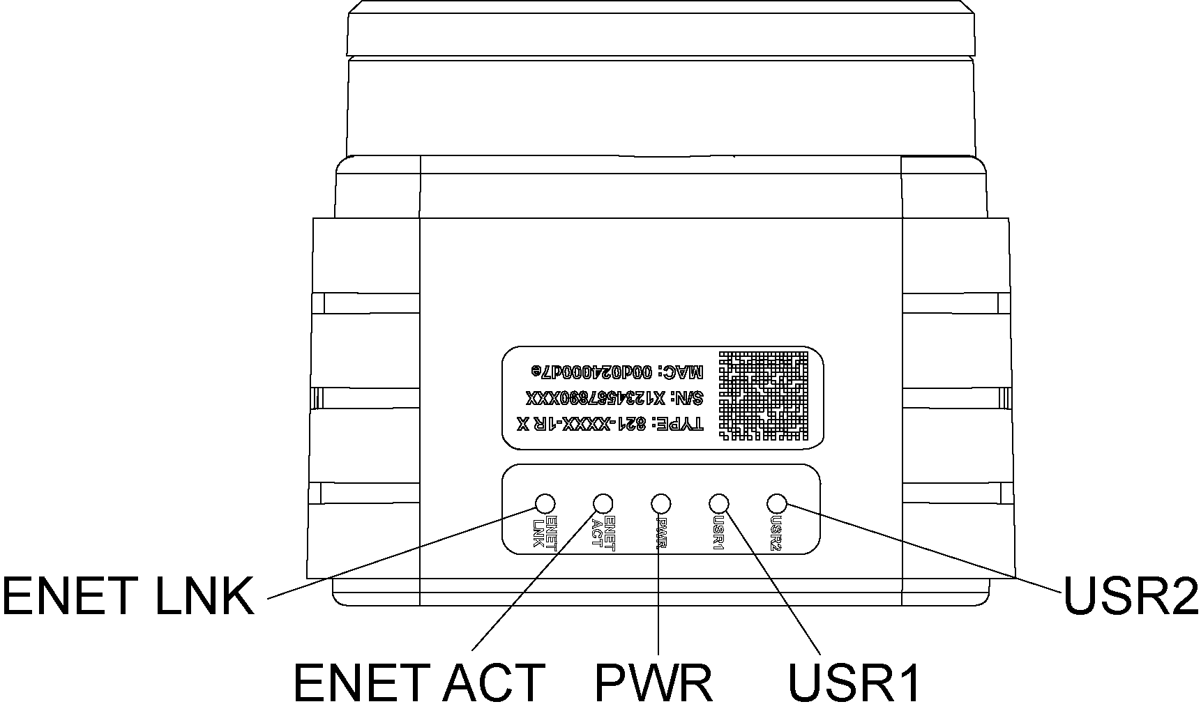
| Indicator | Function |
| ENET LNK LED | Solid green when a network connection is detected. |
| ENET ACT LED | Flashes green when there is network activity. |
| PWR LED | Solid green when power is applied. |
| USR1 LED |
Red when active. User-configurable using Discrete Output Line 5 (Line 13 when using the CIO-MICRO or CIO-MICRO-CC I/O module). |
| USR2 LED |
Green when active. User-configurable using Discrete Output Line 4 (Line 12 when using the CIO-MICRO or CIO-MICRO-CC I/O module). |
Note: If the USR2 LED blinks green three times followed by the USR1 LED blinking red sixteen times, the vision system is not operating correctly. If power cycling does not resolve the problem, please contact Cognex Technical Support.
When utilizing a POWERLINK-enabled In-Sight vision system, the vision system's LEDs are used to convey POWERLINK-specific behavior status updates. The USR1 LED is used as the POWERLINK error LED, and the USR2 LED is used as POWERLINK status LED.
| Indicator | LED Behavior | Function |
|---|---|---|
| USR1 LED | Solid red | POWERLINK is in an error state. |
| USR2 LED | Off | POWERLINK is initializing. |
| Blinking at 10Hz | POWERLINK is in basic Ethernet mode (i.e., a POWERLINK Master Node has not been detected on the network). | |
| One short flash (200ms), followed by a long OFF phase (1000ms) | The vision system has detected a Master Node on the POWERLINK network, however, isochronous communications have not been detected. | |
| Two short flashes, followed by a long OFF phase | The POWERLINK network has begun isochronous communications, but the vision system has not been configured to participate. | |
| Three short flashes, followed by a long OFF phase | The Node device has completed configuration, and is awaiting a signal from the Master Node to begin isochronous communications. | |
| On | The Node device is communicating on the POWERLINK network. | |
| Blinking at 2.5Hz | The POWERLINK Node has stopped due to an error. |