I/O Module Cable
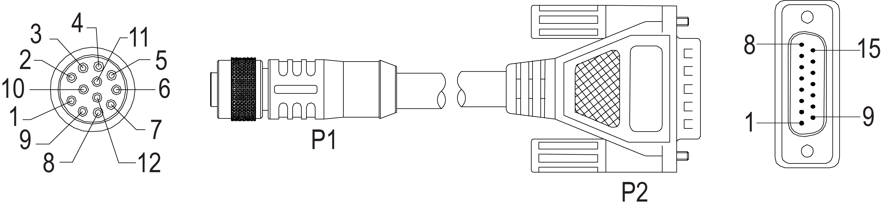
The I/O Module cable connects the vision system directly to a compatible I/O module via the DB15 connector. When the I/O module is used, all power and communication lines used by the vision system are connected using the I/O Module cable.
|
||||
|---|---|---|---|---|
| P1 Pin# | Signal Name | Wire Color | Signal Name | P2 Pin# |
| 1 | IN 2 / HS OUT 2 | Yellow | Not Used | Not Used |
| 2 | RS-232 TRANSMIT | White/Yellow | RS-232 RECEIVE | 7 |
| 3 | RS-232 RECEIVE | Brown | RS-232 TRANSMIT | 6 |
| 4 | IN 3 / HS OUT 3 | White/Brown | Not Used | Not Used |
| 5 | IN 1 | Violet | Not Used | Not Used |
| 6 | COMMON IN | White/Violet | TRIGGER- | 3 |
| 7 | +24VDC | Red | +24VDC | 1 |
| 8 | GND | Black | -24VDC | 8 |
| 9 | COMMON OUT | Green | -24VDC | 8 |
| 10 | TRIGGER | Orange | TRIGGER+ | 2 |
| 11 | HS OUT 0 | Blue | HS OUT 0 | 4 |
| 12 | HS OUT 1 | Grey | HS OUT 1 | 5 |
Note: Cables are sold separately.