I/O Module Cable Specifications
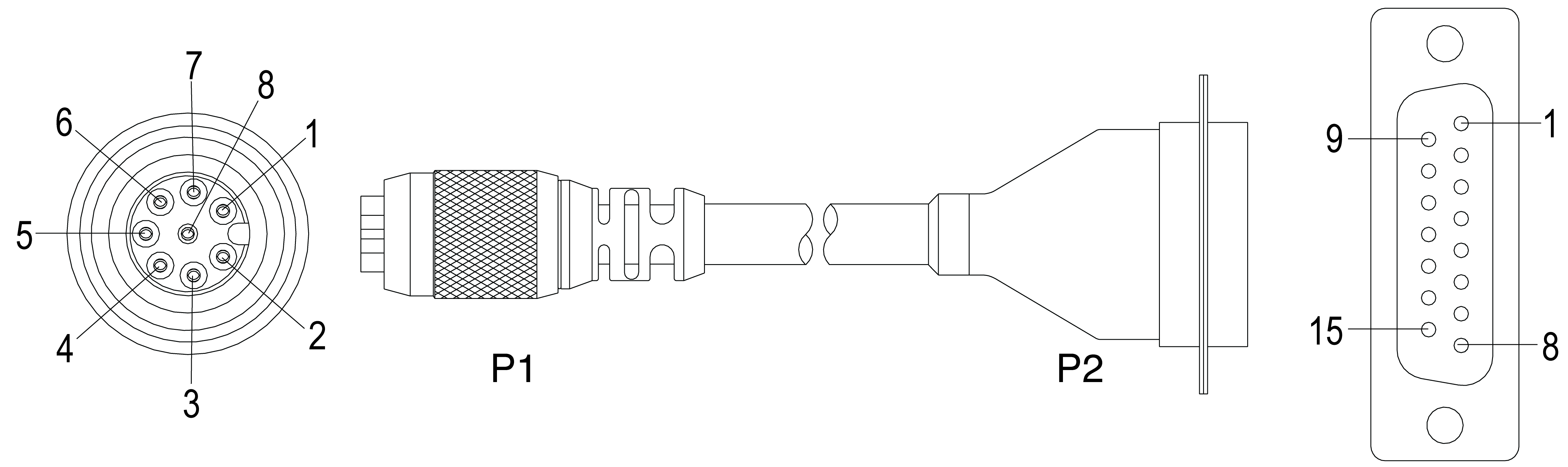
The I/O Module cable connects the vision system directly to a compatible In-Sight I/O module via the DB15 connector. When the I/O module is used, all power and communication lines used by the vision system are connected using the I/O Module cable.
|
||
|---|---|---|
| P1 Pin# | Signal Name | P2 Pin# |
| 1 | +24VDC | 1 |
| 2 | TRIGGER+ | 2 |
| 3 | TRIGGER- | 3 |
| 4 | HSOUT 0 | 4 |
| 5 | HSOUT 1 | 5 |
| 6 | RS-232 RECEIVE (RxD) (In-Sight 5604 Only: Encoder A) |
6 |
| 7 | RS-232 TRANSMIT (TxD) (In-Sight 5604 Only: Encoder B) |
7 |
| 8 | 24V COMMON | 8 |
Note:
- Cables are sold separately.
-
Access to the encoder inputs on the In-Sight 5604 Line Scan are not supported by the CIO-MICRO or CIO-MICRO-CC I/O module.
- Refer to your specific I/O module installation manual for more connection information.