Connect the Power and I/O Breakout Cable
The Power and I/O Breakout cable must be used to supply power to the In-Sight 7000 series vision system. The Power and I/O Breakout cable also provides access to the vision system's trigger, general-purpose inputs, high-speed outputs and RS-232 communications. Refer to the In-Sight® 7000 Series Vision System Installation Manual for more information.
Note:
- The power supplies for the vision system and I/O module can be combined into a single power supply, provided the single power supply meets the capacity requirements of the two devices.
- When you configure the In-Sight 7000 series vision system for use with the CIO-MICRO or CIO-MICRO-CC I/O module, the RS-232 TRANSMIT and RS-232 RECEIVE pins on the Breakout cable are disabled. To connect to a serial device, use the I/O module's RS-232 port (DB9). Refer to Connect an RS-232 Serial Cable (Optional).
- You can clip unused wires short or use a tie made of non-conductive material to tie them back.
- Verify that the vision system's 24VDC power supply is unplugged and not receiving power.
- Optionally connect the Power and I/O Breakout cable's I/O wires to an appropriate device (for example, a PLC). Refer to the In-Sight® 7000 Series Vision System Installation Manual for more information.
-
Attach the Breakout cable's +24VDC (Red wire) and GND (Black wire) to the corresponding terminals on the power supply.
CAUTION: Never connect voltages other than 24VDC. Always observe the polarity shown. -
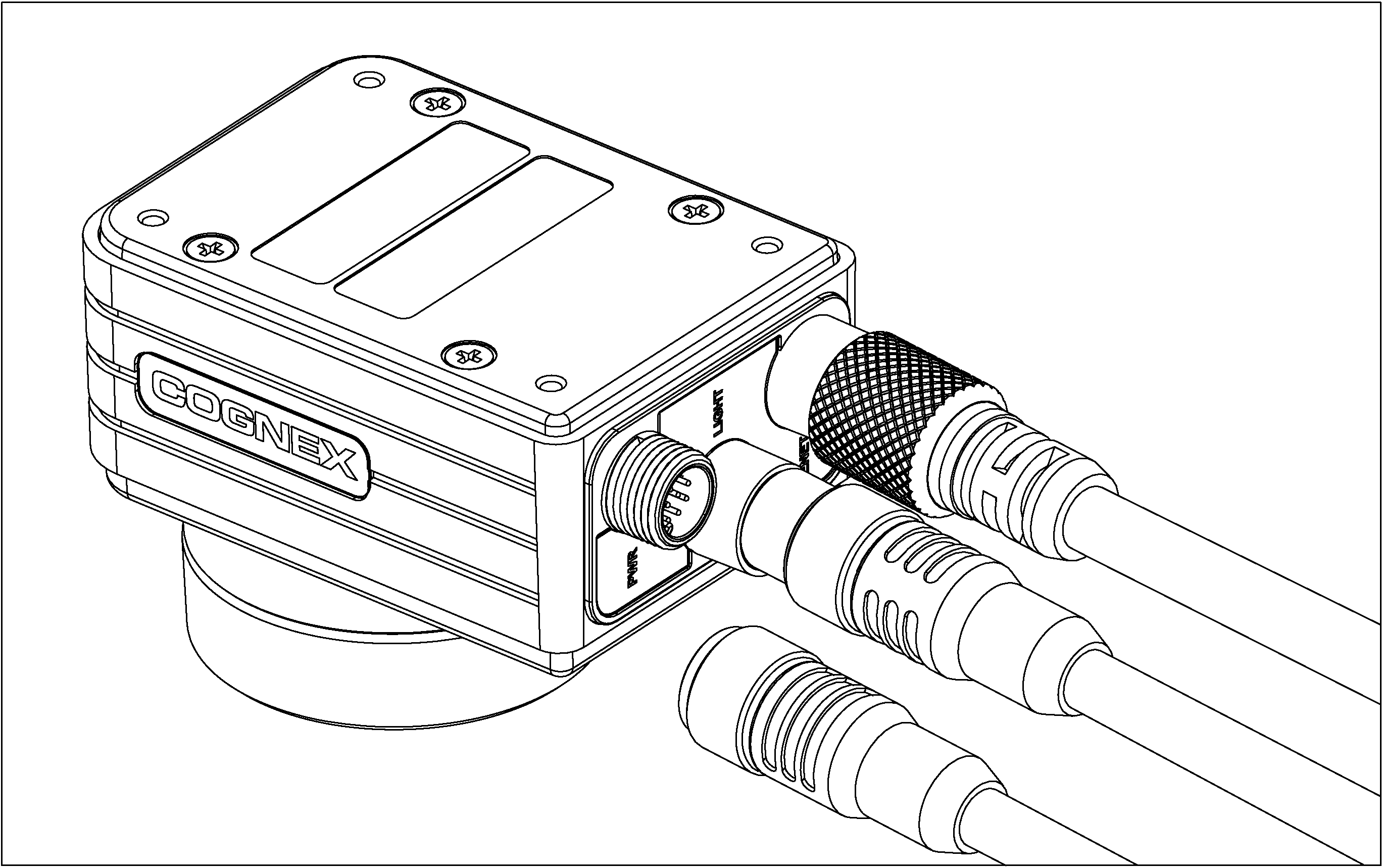
Connect the Breakout cable's M12 connector to the vision system PWR connector.
- Restore power to the vision system’s 24VDC power supply and turn it on if necessary.
- Restore power to the I/O module’s 24VDC power supply and turn it on if necessary.
- Use In-Sight Explorer software to configure the vision system and I/O module. For more information, refer to the In-Sight® Explorer Help file, which is available from the Help menu or by pressing the F1 key.