Connect the CIO-1400 I/O Expansion Module (Optional)
Note:
- When connected to the CIO-1400 I/O expansion module:
- HS OUT 0 and HS OUT 1 are configurable as NPN (current sinking) with 50mA maximum current and the general-purpose outputs are configurable as NPN (current sinking) or PNP (current sourcing) with 100mA maximum current.
- The 9902Lvision system's ENCODER A INPUT, ENCODER B INPUT and IN 1 lines are not supported.
- The 9912 vision system's IN 1, IN 2 / HS OUT 2, and IN 3 / HS OUT 3 lines are not supported.
- Perform wiring or adjustments to I/O devices when the vision system is not receiving power.
|
|
|---|---|
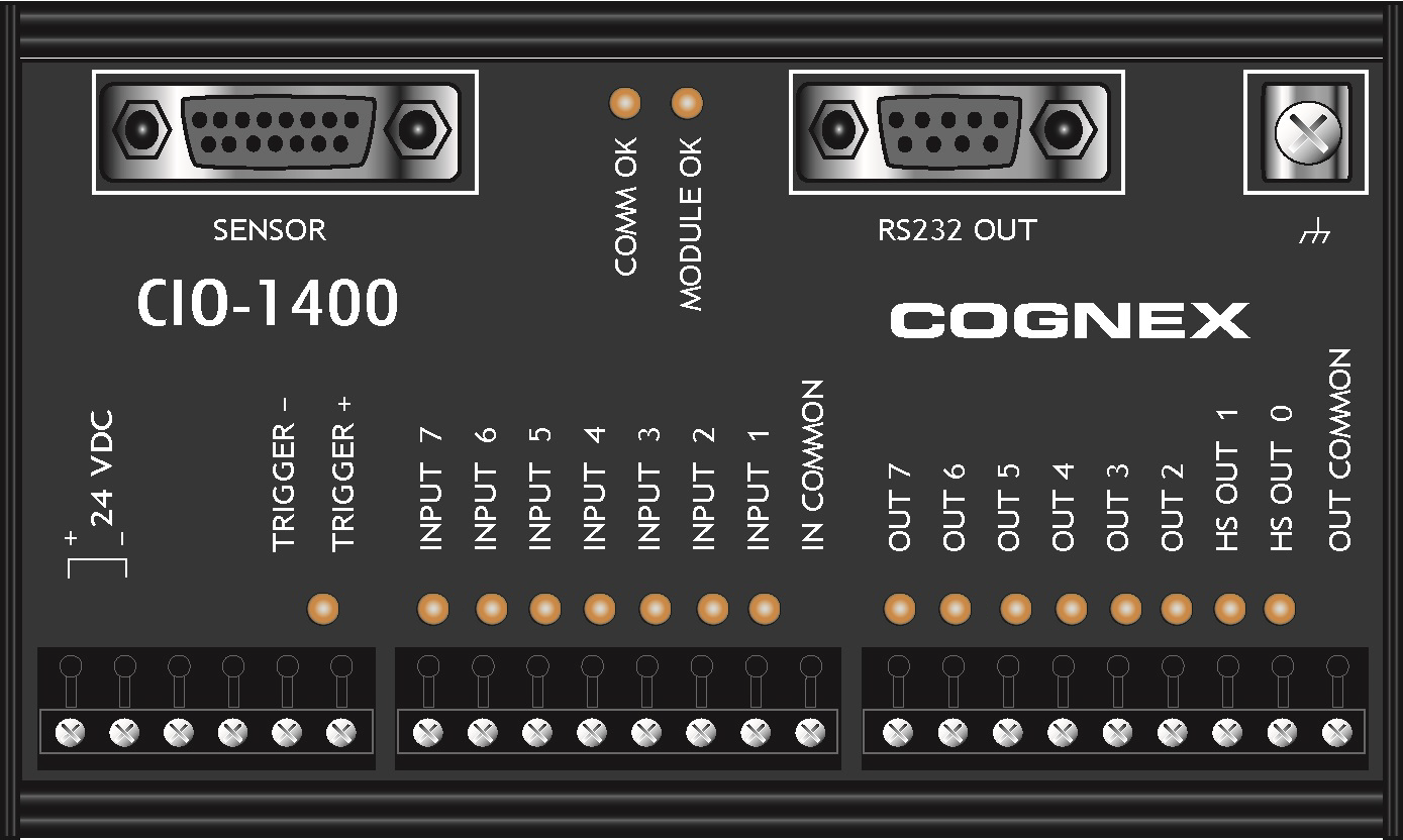
| Connector/Indicator | Description |
| COMM OK LED (yellow) | Illuminates to indicate that the vision system and I/O module are communicating properly. |
| MODULE OK LED (yellow) | Illuminates after the I/O module has initialized and is ready to communicate with the vision system. |
| I/O and Trigger Status LEDs (yellow) | Illuminates to indicate when an input/output has switched ON. |
| SENSOR Port | Connects the I/O module to the vision system using the I/O Module cable, which provides power, trigger, I/O and RS-232 signals to the vision system. |
| RS232 OUT Port | Connects the I/O module to an RS-232 serial cable, which provides RS-232 communications between the I/O module and an external serial device. |
|
Frame Ground Terminal |
Connects the I/O module to a common frame ground. |
-
Connect the I/O module's power wires.
CAUTION: Never connect the I/O module to a power source other than 24VDC. Any other voltage creates a risk of fire or shock and can damage the hardware. Do not connect the 24VDC power source to any terminals other than the 24VDC + and – power terminals.- Verify that the 24VDC power supply is unplugged and not receiving power.
- Use a screwdriver to loosen the I/O module's power terminals (labeled 24VDC + and –).
- Insert the 24VDC + and – wires (16 - 26 AWG, solid or stranded wire) from the power supply into the 24VDC + and – terminals on the I/O module.
- Tighten the screw terminals with the screwdriver to secure the wire leads in the terminal block. The maximum torque is 0.4 Nm (3.5 in-lb).
-
Connect a frame ground wire to the I/O module’s Frame Ground terminal. Connect the other end of the frame ground wire to frame ground.
CAUTION: The shield ground connections of the RS232 OUT port, SENSOR port and Frame Ground terminal are internally connected. The system grounding is designed to be at a zero ground potential; this zero ground potential extends through the cable and to peripheral equipment (e.g. a vision system, PLC, etc.). To ensure safe operating conditions, it is strongly recommended that all ground connections are checked to ensure that a zero ground potential is met. - Connect the I/O module's I/O wires.
- Determine how I/O devices will be connected to the I/O module’s input and output terminals.
- To loosen the appropriate screw terminals, use a screwdriver.
- Connect the input and output wires to the input and output terminals.
- Connect the other end of the input and output wires to the corresponding I/O device.
- Tighten the screw terminals with the screwdriver to secure the wire leads in the terminal block. The maximum torque is 0.4 Nm (3.5 in-lb).
- To connect the vision system to a serial device, plug an RS-232 serial cable (DB9 male connector) into the I/O module’s RS232 OUT port and connect the other end of the cable to the serial device. Tighten the connector screws to secure it to the I/O module.
- Connect the I/O Module cable (CCB-PWRIO-MOD-xx) to the vision system.
- Connect the I/O Module cable’s M12 connector to the vision system’s PWR connector.
- Connect the I/O Module cable’s DB15 connector to the I/O module’s SENSOR port.
- Restore power to the 24VDC power supply and turn it on if necessary.