5100 and 5400 Series Vision System Ethernet Cable Specifications
The Ethernet cable is used to connect the vision system to other network devices. The Ethernet cable can be connected to a single device or provide connections to multiple devices via a network switch or router.
|
|||
|---|---|---|---|
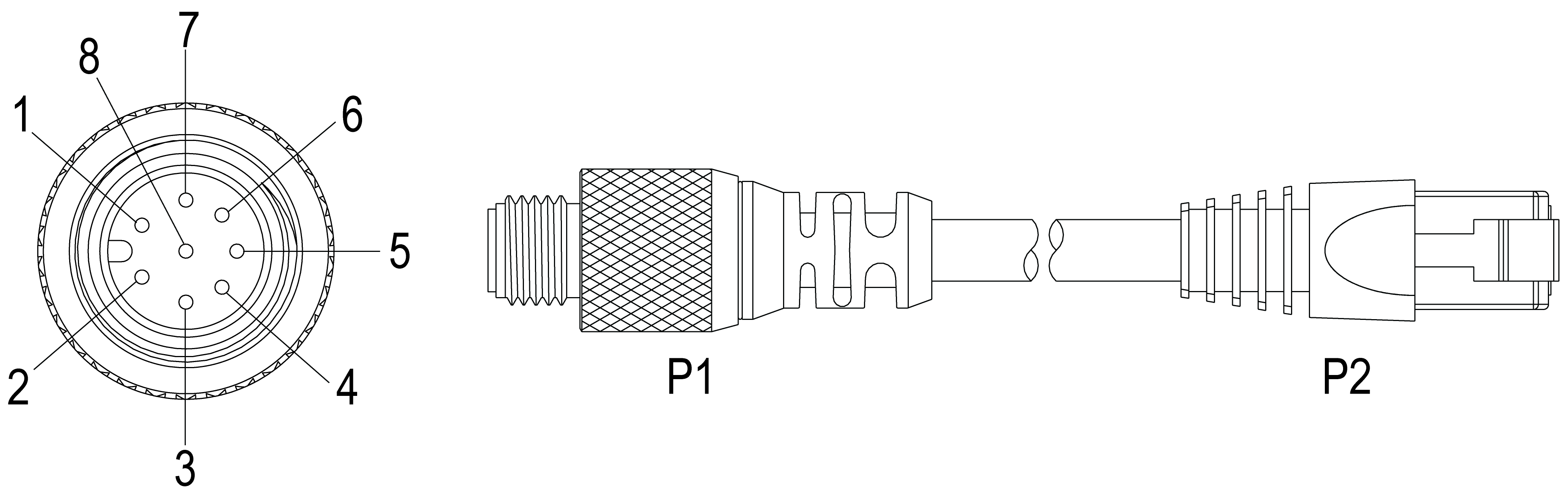
| P1 Pin# | Signal Name | Wire Color | P2 Pin# |
| 6 | TPO+ | White/Orange | 1 |
| 4 | TPO- | Orange | 2 |
| 5 | TPI+ | White/Green | 3 |
| 7 | TRMA | Blue | 4 |
| 1 | TRMB | White/Blue | 5 |
| 8 | TPI- | Green | 6 |
| 2 | TRMC | White/Brown | 7 |
| 3 | TRMD | Brown | 8 |
Note:
- Cables are sold separately.
- The wiring for this cable follows standard industrial Ethernet M12 specifications. This varies from the 568B standard.