 Adjusting the Pixel Count Presence/Absence Tool Parameters
After the tool’s region has been positioned, you can optimize the tool for your application.
Displays a green circle  or a red rectangle
  to indicate success and failure, respectively.
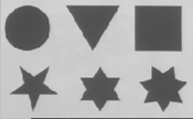
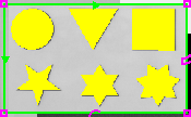
Defines how the tool segments the image into areas of black pixels and white pixels. By default, the tool counts the black pixels, and the black pixels are highlighted yellow in the region.
| Original Image |
|
| Selected Pixel Color = Black | |
|
|
The left handle sets the low threshold value (0 - 255) and the right handle sets the high threshold value (0 - 255). You can manually set the values by adjusting the handles or by entering values in the corresponding edit boxes.
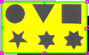
To count white pixels, press ![]() . Now the white pixels are highlighted yellow in the selected region.
. Now the white pixels are highlighted yellow in the selected region.
| Selected Pixel Color = White | |
|
|
Automatically sets the range limits to be the most recent tool result, +/- 10% of the maximum result value for the tool. For example, if the maximum result value for the tool is 255 and the most recent tool result is 150, then clicking the Auto button will set the minimum range limit to 125 (=150 - 25), and the maximum range limit to 175 (=150 + 25).
Defines the acceptable number of pixels in the region. The handles set the minimum and maximum number of black or white pixels that must be counted within the range limits in order for the tool to pass.
| PASS |
|
| FAIL |
|
If the Result falls between the left and right handles, the tool passes and the green border is displayed around the meter. Otherwise, the tool fails and the red border is displayed around the meter.
You can manually set the values by adjusting the handles or by entering values in the corresponding edit boxes.
When enabled, the tool fails if the result falls within the range limits. (Default = Off)
|
Pass/Fail |
|
 (Invert) (Invert) |
|
Pass/Fail |
|
Pass/Fail |
|
(Invert) |
|
Pass/Fail |
Defines whether or not the counted pixels are always displayed in the image area (highlighted yellow).
- On (
 = default): the counted pixels are always displayed in the image area unless other location or inspection tool is being edited.
 -
Off (
 ): the counted pixels are displayed in the image area only when this tools is being edited.
Changes the color of the pixels to count - Black ![]() or White
or White ![]() (default = Black ).
(default = Black ).
Displays the amount of time, in milliseconds, that the tool took to perform its inspection. This time may vary, depending upon the complexity of the scene in the image, as well as the position of the feature within the image, and the amount of variance allowed in the parameters.
Defines the name of your inspection tool. ,The default name is “Pixels_1” (if it is the first Pattern tool added to the job, otherwise it will be incremented, e.g. “Pixels_2”, “Pixels_3”, etc.).
Defines which image the tool will utilize to perform its inspection; the unfiltered, acquired image (the default setting), or the output image of an Image Filter Tool. This control is only enabled if an Image Filter Tool has been added.
Defines whether or not the tool's pass/failure status should be included in the job's overall pass/fail status; by default, it is checked and will be included in the job's overall pass/fail status. Uncheck the check box to keep the tool's pass/failure status separate from the other tools in the job. This control should be unchecked if a tool is expected to fail; for example, if two PatMax Patterns Identification Tools were being used to determine whether or not the part was a right-hand or left-hand part, one of the tools would be expected to fail every time. This situation would result in the job failing every time, regardless of which side of the part was identified, were the checkbox checked.
Defines when and whether or not the inspection tool should run (default setting is “On”).
- Select “Off” if you want to disable the tool.
- Select an Input line if you want the tool tied to a specific discrete input line, where it can be turned On or Off (a High signal, 1, is On, a Low signal, 0, is Off). Connecting the tool to an input allows a control system, such as a PLC, to determine which tools should run, and when.
Selects a fixture for the tool. The Fixture button turns orange when the fixture control is enabled.
A comment that describes the purpose of the tool (by default, the field is blank). Up to 255 alpha-numeric characters or 127 Asian language characters may be used.