Encoder Specifications
The vision system typically relies on electrical signals from an encoder to generate images, allowing the vision system to capture image information based on the speed of the moving object rather than predetermined acquisition timing. Many vision applications use a rotary encoder attached to the conveyor system.
- The frequency of encoder pulses must not exceed 1000 kHz.
- Using an encoder allows you to specify input and output delay values in pulse counts instead of real time units.
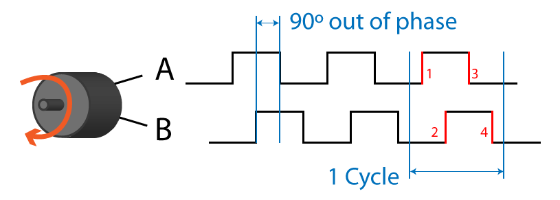
A quadrature rotary encoder uses two output channels (A and B) to provide cyclical outputs as the encoder rotates. The signals are quadrature outputs - 90 degrees out of phase with each other. Each complete quadrature cycle consists of four rising or falling pulse edges. The number of cycles per encoder rotation depends on the specific encoder you use.
| Signal A and B in Quadrature |
|---|
|
The distance per cycle is the physical distance that the conveyor system needs to travel to cause the encoder to output one full cycle. This distance can be calculated based on the dimensions of your encoder and the length of the image you want to acquire.
The vision system supports single-channel and quadrature encoders.
- Single-channel encoders generate only one signal (A). Be aware that single-channel encoders cannot determine which direction the conveyer system is moving.
Software features that manage encoder resolution do not apply to single-channel encoding.
A DS1000 sensor increments the encoder count by one for each complete encoder cycle.
A L38 sensor increments the encoder count by two for each complete encoder cycle.
-
Quadrature encoders use two channels (A and B) to specify the direction of motion. L38 uses the following convention for determining the direction of motion:
- Positive: PHA leads PHB
- Negative: PHA lags PHB