3D-L4000Series Image Viewer – 3D Mode
When set to 3D mode with the 3D button, the image viewer of the 3D-L4000 Series Acquisition Wizard shows the 3D point cloud constructed from the 2D profiles acquired by the device.
The Display Area shows the 3D point cloud according to the settings configured on the Display Toolbar. It also allows you the free-hand manipulation of the view configured with the Toolbar buttons:
- Hold the left mouse button and move the mouse cursor in the Display Area to rotate the camera with respect to the point cloud.
- Use the mouse wheel to zoom in or out of the point cloud.
- Hold the Shift key and the left mouse button to pan the 3D scene.
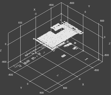
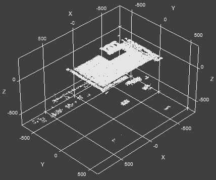
The screen also has a Rotation Compass, showing the direction of the X, Y and Z axes and planes relative to the current perspective. Left-click on any of the colored planes of the compass to snap the view direction to that respective plane.

For example, clicking on the red X-plane of the compass snaps the view direction on the X-plane. The selection is indicated with yellow color.
In this view, the toolbar has the following controls:
| Icon | Description | |||||
|
|
Fit 3D Image to Window |
Fits the 3D point cloud to the display. The point cloud will automatically scale to be maximally displayed in the viewer. The original aspect ratio of the point cloud is also maintained, therefore it may not fill the viewer completely. |
||||
|
|
Show 2D texture overlay |
Enables you to toggle between 2D and 3D views of the point cloud. Clicking on the Show 2D texture overlay button enables the 2D overlay on the point cloud. |
||||
|
|
Slider |
When you enable Show 2D texture overlay and Color 3D Image By Height, the slider allows you to modify which parameter has more weight on the representation. When the slider is on one of the two ends, the visualization is based on either the texture or the height color parameter. |
||||
|
|
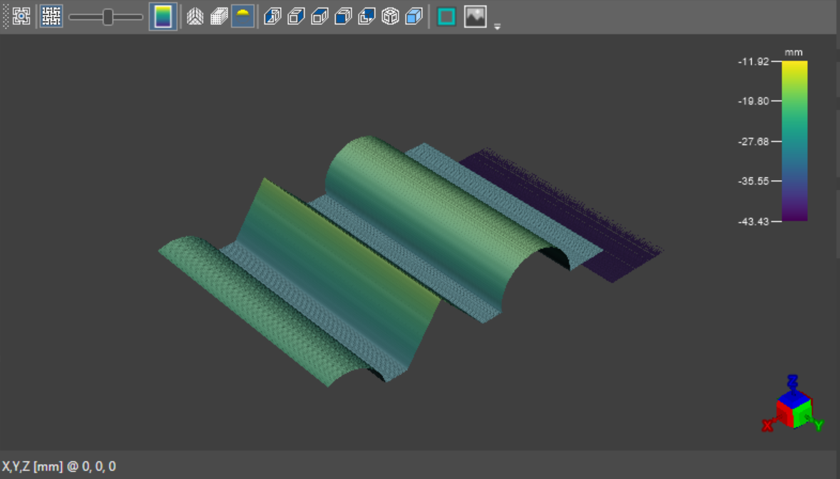
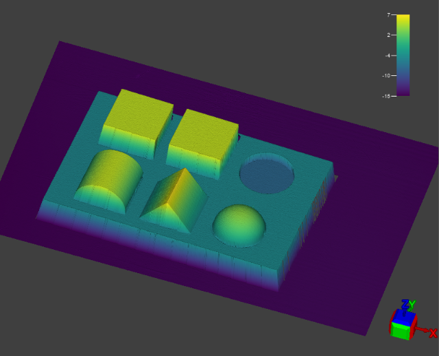
Color 3D Image By Height |
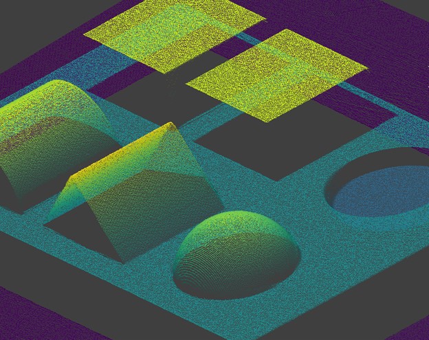
Enables the Z-Axis Height Color Map and the Color Map Legend, indicating the height of the point cloud points along the Z-axis, relative to the height coloring setup in the Spreadsheet Editor.
When color mapping is enabled, the warmer the point is, the closer it is to the top threshold (i.e., it is "higher" in the working space of the sensor). Consequently, the colder it is, the closer it is to the bottom threshold (i.e. the lower it is in the working area of the sensor). |
||||
|
|
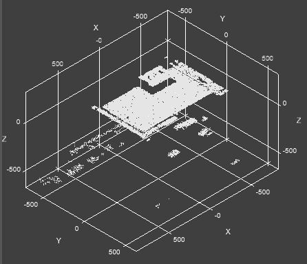
Toggle 3D Grid |
Toggles a 3D grid around the point cloud, indicating the planes, axes and distances within the point cloud space.
|
||||
|
|
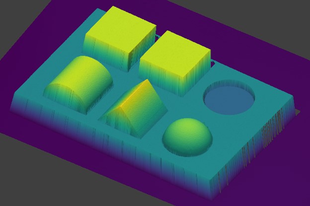
Toggle 3D Image Visualization as Points/Surface |
Allows you to switch between Mesh Mode (
|
||||
|
|
Toggle Lambert Lighting |
Toggles ambient directional Lambert lighting in the 3D scene. When turned off, lighting is cast from the Z-axis. When toggled, it comes from the 3D viewer camera perspective. Tip: Enable or disable this setting based on which features of the acquired point cloud you wish to be visible.
|
||||
|
|
Show 3D Image From Left |
Changes the view to display the point cloud on the Y and Z-axes, in a reverse X-axis direction (in other words, shows the point cloud "from the left"). |
||||
|
|
Show 3D Image From Right |
Changes the view to display the point cloud on the Z-axis and a reverse Y-axis, in an X-axis direction (in other words, shows the point cloud "from the right"). |
||||
|
|
Show 3D Image From Top | Changes the view to display the point cloud on the X and Y axes, in a reverse Z-axis direction. In other words, this view shows the point cloud "from the top", from the perspective of the camera sensor. | ||||
|
|
Show 3D Image From Front |
Changes the view to display the point cloud on the Z-axis and a reverse X-axis, in a reverse Y-axis direction. In other words, this view shows the point cloud "from the front", and the orientation on-screen is as if looking at the inspected part facing from camera-to-laser in front of the 3D vision system. |
||||
|
|
Show 3D Image From Back | Changes the view to display the point cloud on the X and Z-axes, in a Y-axis direction. In other words, this view shows the point cloud "from the back side", and the orientation on-screen is as if looking at the inspected part facing from camera-to-laser behind the 3D vision system. | ||||
|
|
Show 3D Image Isometrically | Changes the view to isometric, with all three coordinate axes appearing equally foreshortened, and the angle between any two of them being 120 degrees. This is the default perspective.
|
||||
|
|
Orthographic / Perspective Toggle |
Allows you to switch between the orthographic and perspective views of the acquired image data.
|
||||
|
|
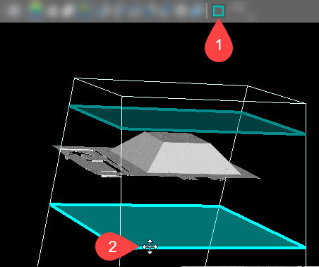
Edit ROI |
Shows or hides the device's working space. Enable this setting if you want to position the object to ensure that it is completely located within the device's working space. Tip:
You can also modify the detection zone when this setting is enabled. Simply click and hold either the top or bottom Z-plane of the detection zone (shown in blue) to drag it to the desired position.
|
||||
|
|
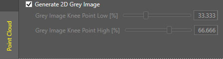
Change 3D/Grey Display |
The Change 3D/Grey Display button changes the representation from 3D Pointcloud to 2D texture. The Change 3D/Grey Display button is only available if you enable Generate 2D Grey Image first.
|


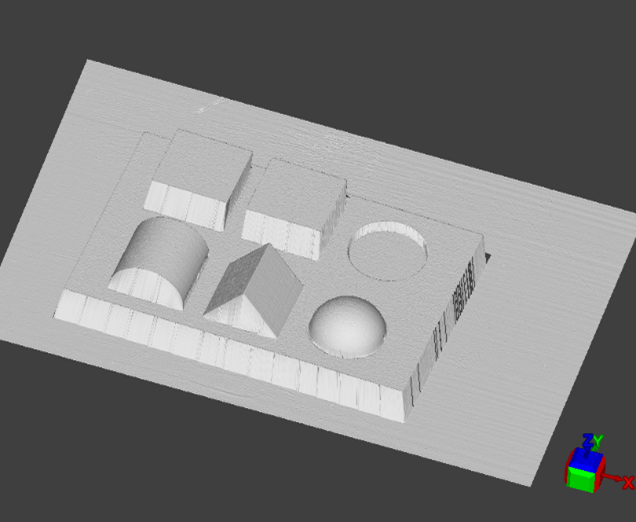


 ) in the 3D viewer as shown below. This setting is disabled if the