InspectEdgeForDefect

Used to construct an edge model to perform advanced edge analysis on the edges or edge pairs returned by an InspectEdge function. This data is used to construct a best-fit line fit to compare found edges or edge pairs against, detecting defects and gaps, such as the distance from the line fit.

InspectEdgeForDefect Overview

After inserting the function into the spreadsheet, a reference must be made to an Inspect data structure output by an InspectEdge function. Once the reference to the InspectEdge function is established, the edge model is created by configuring the parameters of the InspectEdgeForDefect function. The edge model involves defining the following:

  • The type of line fit - straight or circular.
  • The type of edge - single or edge pair.
  • The type of edge transition - white to black or vice-versa.
  • The edge scoring criteria that will be used to filter unwanted edges.
  • The line fit criteria that will be used to filter unwanted edges from the line fit.
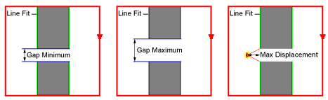
  • The tolerances for defects or gaps to be encountered.

Once the edge model has been established, the function compares edge candidates against the edge model and report deviations from the model.

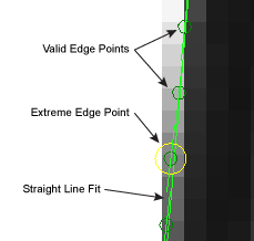
Example - Passing Straight Line Fit Edge

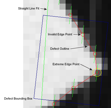
Example - Failing Straight Line Fit Edge

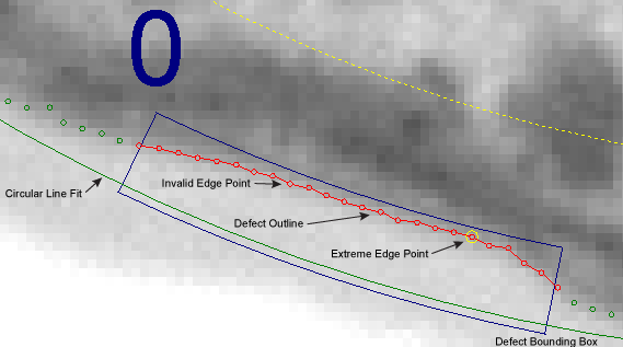
Example - Failing Circular Line Fit Edge

InspectEdgeForDefect Inputs

Parameter Description

InspectEdge

Specifies a reference to a spreadsheet cell that contains a valid Inspect data structure returned by an InspectEdge function.

Line Fit

Specifies the type of line fit to be constructed out of the detected edges.

1 = Straight Line Fit

The function creates straight line fit from the detected edges.

2 = Circle Line Fit

The function creates a circular line fit from the detected edges.

3 = Auto Fit (default)

The function automatically creates either a straight line or circular fit, based on the referenced Region.

Inspect Edge Pairs

Specifies whether or not the function should detect edge pairs. Detected edge pairs are labeled graphically within the image, with the first edge detected being 0, and the second edge being 1.
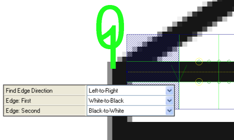
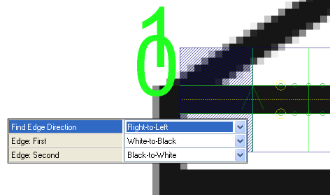
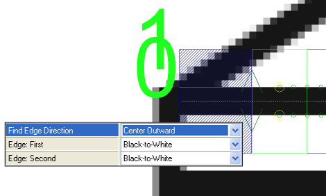
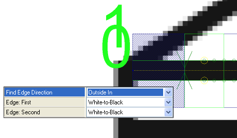
0 = OFF (default)

The function does not detect edge pairs.

1 = ON

The function attempts to detect edge pairs, based upon the Edge Scoring parameters.

Find Edge Direction

Specifies the direction in which the function attempts to detect edges. Dark green arrows are added to graphically illustrate the direction in which the edge is detected. Fit lines are labeled graphically within the image, with the first fit line labeled 0, and the second fit line 1.

Note: If the region of interest (ROI) of the referenced InspectEdge function is bent into a curve, the inspection is relative to the center of the curve. When the Find Edge Direction parameter is set to Left-to-Right, it inspects towards the center of the curve, and when set to Right-to-Left, it inspects away from the center of the curve.

0 = Left-to-Right (default)

The function attempts to detect edges from the left of the ROI to the right.

1 = Right-to-Left

The function attempts to detect edges from the right of the ROI to the left.

3 = Center Outward

The function attempts to detect edges from the center of the ROI to the upper and lower bounds of the ROI (the order of the found edges is in the opposite direction of the "X" arrow on the ROI).

Note: The Inspect Edge Pairs parameter must be ON to enable this selection.

2 = Outside In

The function attempts to detect edges from the upper and lower bounds of the ROI to the center of the ROI (the order of the found edges is in the opposite direction of the "X" arrow on the ROI).

Note: The Inspect Edge Pairs parameter must be ON to enable this selection.

Edge: First

Specifies the contrast transition of the first edge to be detected, as determined by the Find Edge Direction parameter.

1 = Black-to-White

The edge transitions from black pixels to white pixels.

2 = White-to-Black (default)

The edge transitions from white pixels to black pixels.

3 = Either

The edge can transition from either black-to-white, or white-to-black, and the function determines the proper transition. Specifying the transition improves the performance of the function.

Edge: Second

Specifies the contrast transition of the second edge to be detected, as determined by the Find Edge Direction parameter.

Note: The Inspect Edge Pairs parameter must be ON to enable this selection.

1 = Black-to-White (default)

The edge transitions from black pixels to white pixels.

2 = White-to-Black

The edge transitions from white pixels to black pixels.

3 = Either

The edge can transition from either black-to-white, or white-to-black, and the function determines the proper transition. Specifying the transition improves the performance of the function.

Edge Scoring

Specifies the edge scoring mode used to determine whether or not an edge meets the established criteria.

Score Threshold

Specifies a scoring threshold to filter out edges with scores (1 to 100; default = 10) lower than this value.

Edge Rules

Specifies the type of edge that is most important when calculating the score.

1 = First

The first edge detected receives the highest consideration.

2 = Strongest

The edge with the strongest contrast transition receives the highest consideration.

3 = First Strongest (default)

The first edge detected, with the strongest transition, receives the highest consideration.

4 = Edge Pair Size

The edge pair detected with the size closest to the Pair Size parameter receives the highest consideration.

5 = First Edge Pair Size

The first edge pair detected with the size closest to the Pair Size parameter receives the highest consideration.

6 = Strongest Edge Pair Size

The edge pair detected with the strongest transition and the size closest to the Pair Size parameter receives the highest consideration.

7 = First Strongest Edge Pair Size

The first edge pair, with the strongest transition and the size closest to the Pair Size parameter, receives the highest consideration.

Contrast Upper Bound

Specifies the upper limit of the edge contrast transition (2 to 255; default = 255) to be considered an edge. Edges with an edge contrast transition above this value have the same highest score.

Note: The Edge Rules parameter must be set to either Strongest, First Strongest, Strongest Edge Pair Size, or First Strongest Edge Pair Size to enable this parameter.

Pair Size

Specifies the edge pair size at which the highest score is achieved (valid range is 1 to 3 times the image width of the In-Sight vision system; default = 5). When this parameter is enabled, edge pairs detected above or below this value are scored proportionally to this value. For example, if the Pair Size is set to 10, and two edge pair candidates are detected, one with a value of 8 and another with 14, the edge pair with a value of 8 is selected because it is closer to the limit than the second edge pair.

Note: The Inspect Edge Pairs parameter must be On, and the Edge Rules parameter must be set to either Edge Pair Size, First Edge Pair Size, Strongest Edge Pair Size, or First Strongest Edge Pair Size to enable this parameter.

Advanced Line Fit

Specifies how the function should construct the line fit.

Filter Outliers

Specifies that the function removes points from the Fit Line that are further than the distance specified in the Fit Distance Filter parameter.

0 = OFF (default)

The function does not account for outlier edges.

1 = ON

The function accounts for outlier edges in its calculation.

Fit Distance Filter

Specifies the distance, in pixels (valid ranges are 1 to 3 times the image width of the In-Sight vision system; default = 2), from which an edge must be from the original Fit Line to be utilized in a re-fit calculation. This setting is useful in helping to prevent defects from affecting the line fit. Filter Outliers must be ON to enable this setting.

Furthest Point Filter Distance

Specifies the distance an outlier can be from the line fit and still considered a part of the line fit (valid ranges are 1 to 3 times the image width of the In-Sight vision system; default + 3). Any edge which is greater than this value will be ignored.

Re-Score

Specifies that the edges are re-scored to select edges which are closer to the line fit.

0 = OFF (default)

The function does not re-score the edges to account for outliers.

1 = ON

The function re-scores the edges to account for outlier edges in its calculation.

Re-Fit

Specifies that the function re-fits the line fit after the edges have been re-scored. Enabling this functionality helps the accuracy of the line fit, however it adds processing time.

0 = OFF (default)

The function does not attempt to re-fit the line fit.

1 = ON

The function re-fits the line fit after the edges have been re-scored.

Max Number of Defects/Gaps

Specifies the maximum number of defects and gaps the function should expect to detect (1 to 4096; default = 5). This value is applied to Defects and Gaps individually. For example, when the setting is 5, the function expects to encounter a maximum of 5 Defects and 5 Gaps. This setting is used to construct the Vision Data Access Result Table in the spreadsheet.
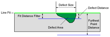
Defects

Specifies the parameters for determining defects in the edge from the line fit.

Min Distance

Specifies that any distance, in pixels (valid ranges are 0.001 to 3 times the image width of the In-Sight vision system; default = 3 pixels), from the edge and the line fit less than this value is not a defect.

Max Distance

Specifies that any distance, in pixels (valid ranges are 0.001 to 3 times the image width of the In-Sight vision system; default = 3 times), from the edge and the line fit greater than this value is not a defect.

Note: If this value is less than the Min Distance parameter, the function results in a #ERR.

Size Enabled

Specifies whether or not the function accounts for size defects. Size defects account for the length along the edge.

Note: When Size Enabled and Area Enabled are both ON, only defects which fail both conditions will be displayed.

0 = OFF

The function does not account for size defects.

1 = ON (default)

The function accounts for size defects, based on the Min Size and Max Size parameter settings.

Min Size Specifies the minimum defect size, in pixels (valid ranges are 0.001 to 3 times the image width of the In-Sight vision system; default = 3 pixels). Continuous deviations from the line fit which are less than this value are not considered defects.
Max Size Specifies the maximum defect size, in pixels (valid ranges are 0.001 to 3 times the image width of the In-Sight vision system; default = 3 times). Continuous deviations from the line fit which are greater than this value are not considered defects.
Area Enabled

Specifies whether or not the function accounts for area defects. Area defects account for the length along the line fit and how far the defective edge is from the line fit.

Note: When Size Enabled and Area Enabled are both ON, only defects which fail both conditions will be displayed.

0 = OFF

The function does not account for area defects.

1 = ON (default)

The function accounts for area defects, based on the Min Area and Max Area parameter settings.

Min Area Specifies the minimum area defect, in pixels (valid range is from 0.000 to 1000000; default is 10). An area less than this value is not considered a defect.
Max Area Specifies the maximum area defect, in pixels (valid range is from 0.000 to 1000000; default is 1000000). An area greater than this value is not considered a defect.
Defect Line Fit Filter

Specifies whether or not to filter defects based on their position relative to the line fit.

0 = No Filter (default) The function returns defects on both sides of the line fit.
1 = Ignore Left of Line Fit The function filters the left side defects, only returning defects found on right side of the line fit.
2 = Ignore Right of Line Fit The function filters the right side defects, only returning defects found on left side of the line fit.
Sort Criteria

Specifies how the detected defects will be sorted.

By Size (default)

The function sorts detected defects by their size, from the largest to smallest.

By Area

The function sorts detected defects by their area, from the largest to smallest.

By Position The function sorts detected defects by their Caliper index.

Gaps

Specifies the parameters for determining gaps in the edge.

Enabled

Specifies whether or not the function accounts for gaps in the found edge.

0 = OFF

The function does not account for gaps.

1 = ON (default)

The function accounts for gaps, based on the other Gaps parameter settings.

Gap Minimum

Specifies the minimum gap, in pixels (valid ranges are 0.001 to 3 times the image width of the In-Sight vision system; default = 3 pixels). Gaps less than this value are not considered to be gaps.

Gap Maximum

Specifies the maximum gap, in pixels (valid ranges are 0.001 to 3 times the image width of the In-Sight vision system; default = 3 times). Gaps greater than this value are not considered to be gaps.

Max Displacement

Specifies the maximum displacement, in pixels (valid ranges are 1 to 3 times the image width of the In-Sight vision system; default = 3 times), from the line fit to be considered a gap. This setting acts as a filter to remove edges which are detected but are not along the same line fit as the other detected edges.

Note: If the Inspect Edge Pairs parameter is enabled, the maximum displacement is measured, in pixels, from the center of the region to the center of the edge pair. If this distance is more than the Max Displacement parameter value, it is considered a gap.
Ignore Gap Ends

Specifies whether or not the function accounts for gaps detected at the beginning and end of the ROI.

0 = OFF

The function does not account for gaps detected at the beginning and end of the ROI.

1 = ON (default)

The function accounts for gaps detected at the beginning and end of the ROI.

Sort Criteria

Specifies how the detected gaps are sorted.

By Size (default)

The function sorts detected gaps by their size, from the largest to smallest.

By Position

The function sorts detected gaps by their Caliper index.

Caliper Index

Specifies the Caliper displayed on the image (the Caliper is outlined in green). The default Caliper displayed is 0.

Show

Specifies the display mode for the graphical overlays of the function on top of the image.

0 = hide all (default)

All graphics are hidden, except when the cell containing the InspectEdgeForDefect function is highlighted in the spreadsheet.

1 = result graphics only

The line fit, detected defects, outlier points, and gaps are be displayed at all times.

2 = result graphics and found edge

The line fit, detected defects, outlier points, gaps. and detected edge points are displayed at all times.

3 = result graphics and caliper detail

The line fit, detected defects, outlier points, gaps, detected edge points, and the indexed Caliper window are displayed at all times.

4 = show all: input and result graphics

Both the input region, line fit, detected defects, outlier points, gaps, and detected edge points are displayed at all times.

InspectEdgeForDefect Outputs

Returns

An Inspect data structure containing the detected defects, extremes, and gaps, or #ERR if any of the input parameters are invalid.

Results

When InspectEdgeForDefect is initially inserted into a cell, a results table is created in the spreadsheet, and the result table corresponds to the type of search being performed.

Note: If the value of the Max Number of Defects/Gaps parameter is greater than zero, InspectEdgeForDefect automatically inserts a result table containing a maximum of 10 entries that correspond to the first 10 defects/gaps/edges/edge pairs in the data structure. If you wish to display more entries, you can expand the table by copying the last row and pasting additional rows at the end.

The following InspectEdge Vision Data Access functions are automatically inserted into the spreadsheet to create the InspectEdgeForDefect data structure result table, which is broken into four sections, Summary, Defects, Gaps and Extremes:

Spreadsheet Name

Function Name

Description

Summary

Defects/Gaps GetDefectGapCount(Inspect, Defect/Gap, Size/Area, Edge Pair Index) Returns the number of defects/gaps, depending on which is specified. Defects = 0, Gap = 1; Size = 0, Area = 1.
X 0/1 GetFitEdgeX(Inspect, Edge Pair Index, Point Index, Edge Index) Returns the x-coordinate of the specified point.
Y 0/1 GetFitEdgeY(Inspect, Edge Pair Index, Point Index) Returns the y-coordinate of the specified point.
Center X GetFitEdgeCenterX(Inspect, Point Index) Inserted when a Circle Line Fit is specified, returns the x-coordinate of the center of the circle line fit.
Center Y GetFitEdgeCenterY(Inspect, Point Index) Inserted when a Circle Line Fit is specified, returns the y-coordinate of the center of the circle line fit.
Radius GetFitEdgeRadius(Inspect, Edge Pair Index, Point Index) Inserted when a Circle Line Fit is specified, returns the distance from the center of the circle line fit for the selected Edge Pair.
Defects/Gaps
Size/Area GetDefectGapValue(Inspect, Defect/Gap Index, Defect/Gap, Edge Pair Index, Size/Area/Width) Returns the size or area of the defect or gap.Defect = 0, Gap = 1; Size = 0, Area = 1, Width = 2.
X GetDefectGapBoundsX(Inspect, Defect/Gap Index, Defect/Gap, Edge Pair Index) Returns the x-coordinate of the bounding rectangle of the defect.
Y GetDefectGapBoundsY(Inspect, Defect/Gap Index, Defect/Gap, Edge Pair Index) Returns the y-coordinate of the bounding rectangle of the defect.
Height GetDefectGapBoundsHeight(Inspect, Defect/Gap Index, Defect/Gap, Edge Pair Index) Returns the height of the bounding rectangle of the defect.
Width GetDefectGapBoundsWidth(Inspect, Defect/Gap Index, Defect/Gap, Edge Pair Index) Returns the width of the bounding rectangle of the defect.
Angle GetDefectGapBoundsAngle(Inspect, Defect/Gap Index, Defect/Gap, Edge Pair Index) Returns the angle of the bounding rectangle of the defect.
Curve GetDefectGapBoundsCurve(Inspect, Defect/Gap Index, Defect/Gap, Edge Pair Index) Returns the curve of the bounding rectangle of the defect.
Start/End GetDefectGapCaliperIndex(Inspect, Defect/Gap Index, Defect/Gap, Edge Pair Index, Defect Start/End) Returns the Caliper in which the defect starts or ends (Start = 0, End = 1).
Extremes - Furthest Point 1/2
Caliper GetExtremePoints(Inspect, Edge Pair Index, Near/Far) Returns the index of the Caliper whose edge is furthest from the line fit (Near = 0 and Far = 1).
X GetEdgeX(Inspect, Caliper Index, Edge Pair Index or Edge Index) Returns the x-coordinate of the referenced edge.
Y GetEdgeY(Inspect, Caliper Index, Edge Pair Index or Edge Index) Returns the y-coordinate of the referenced edge.
Distance GetEdgeFromFit(Inspect, Caliper Index, Edge Pair Index) Returns the distance from the edge of the referenced Caliper to the line fit.

All of the formulas for the InspectEdgeForDefect conform to the following:

Note:
  • Inspect = An Inspect data structure output by an InspectEdgeForDefect function
  • Caliper Index = 0 to N (the total number of Calipers is equal to the number of Calipers output by the InspectEdge function that the InspectEdgeForDefect function is referencing)
  • Edge Pair Index = 0 or 1
  • Edge Index = 0 to N
  • Point Index = 0 to 1

If the Inspect Edge Pairs parameter is enabled, additional rows of data for Edge 1 are automatically inserted into the spreadsheet. When enabled, an index of 0 returns information regarding Edge 0, and an index of 1 returns information regarding Edge 1.