Modbus TCP Factory Interface
Modbus TCP Data Blocks
The defined data blocks allow you to control where the vision system is reading and writing data to and from the PLC. For easier application setup, the various control and status bits required for command functionality are grouped into contiguous blocks, which can be processed together.
| Block | Byte | Bit 7 | Bit 6 | Bit 5 | Bit 4 | Bit 3 | Bit 2 | Bit 1 | Bit 0 |
|---|---|---|---|---|---|---|---|---|---|
|
Vision Control |
0 |
Set Offline |
Reserved |
Execute Command |
Inspection Results Ack |
Buffer Results Enable |
Trigger |
Trigger Enable |
|
| 1 | Reserved | ||||||||
| 2 | Reserved |
Clear Exposure Complete |
Clear Error |
Initiate String Command |
Set User Data |
||||
| 3 |
External Event 7 |
External Event 6 |
External Event 5 |
External Event 4 |
External Event 3 |
External Event 2 |
External Event 1 |
External Event 0 |
|
|
Vision Status |
0 | Online | Offline Reason |
AcqError |
Reserved |
Trigger Ack |
Trigger Ready |
||
| 1 | Error |
Command Failed |
Command Completed |
Command Executing |
Results Valid |
Results Buffer Overrun |
Inspection Completed |
Reserved |
|
| 2 | Reserved |
Job Pass |
Exposure Complete |
String Command Error |
String Command Ack |
Set User Data Ack |
|||
| 3 |
External Event Ack 7 |
External Event Ack 6 |
External Event Ack 5 |
External Event Ack 4 |
External Event Ack 3 |
External Event Ack 2 |
External Event Ack 1 |
External Event Ack 0 |
|
| Block | Word | Name | |||||||
|---|---|---|---|---|---|---|---|---|---|
|
Input
|
0 | Command | |||||||
| 1 - 2000 | User Data | ||||||||
|
Output |
0 | Current Job ID | |||||||
| 1 |
Error Code |
||||||||
| 2 | Acquisition ID | ||||||||
| 3 | Inspection ID | ||||||||
| 4 | Inspection Result Code | ||||||||
| 5 - 2004 | Inspection Results | ||||||||
|
String Command |
0 | String Command Length | |||||||
| 1 - 960 | String Command | ||||||||
|
String Command Result |
0 | Result Code | |||||||
| 1 |
String Command Result Length |
||||||||
| 2 - 961 | String Command Result | ||||||||
Vision Control Block
Byte 0
| Bit | Name | Description |
|---|---|---|
| 7 | Set Offline |
When this bit is set, the In-Sight vision system is taken Offline until the bit is cleared again. |
| 6-5 | Reserved | Unused. |
| 4 | Execute Command | When set, the vision system either loads the job ID specified in the Command field or executes the Job Load by Name command to load the job name given in the User Data buffer. The signal must be held high until the Command Completed signal is toggled. The falling edge of this signal (if prior to Command Complete) is interpreted as an abort request. |
| 3 | Inspection Results Ack | When the Buffer Results Enable bit is set, the Inspection Results Ack bit is set by the PLC to acknowledge that it has received the Inspection Count, Inspection Result Code and Inspection Results data. The next set of inspection results is then sent to the PLC. Clearing the Inspection Results Ack bit causes the vision system to set the Results Valid bit if the buffer is not empty. |
| 2 | Buffer Results Enable | When this bit is set, the Inspection Count, Inspection Result Code and Inspection Results fields are held constant until they are acknowledged by setting the Inspection Results Ack bit. Up to eight inspections are held in the buffer of the In-Sight vision system. The vision system responds to the acknowledgment by clearing the Results Valid bit. Once the Inspection Results Ack bit is cleared and there is a new set of results sent to the PLC, the Results Valid bit is no longer cleared. If the Inspection Results Ack bit is cleared and there are no more results in the buffer of the vision system that are to be sent to the PLC, the Results Valid bit remains cleared. |
| 1 | Trigger |
Setting this bit triggers an acquisition when the following conditions are met:
|
| 0 | Trigger Enable | This field is set to enable triggering through the Trigger bit. Clear this bit to disable the network triggering mechanism. |
Byte 1
| Bit | Name | Description |
|---|---|---|
| 7-1 | Reserved | Unused. |
Byte 2
| Bit | Name | Description |
|---|---|---|
| 7-4 | Reserved | Unused. |
| 3 | Clear Exposure Complete |
While this signal is High, the Exposure Complete status remains reset. Once this signal is set to Low, the Exposure Complete status is set to High on the next exposure completion. |
| 2 | Clear Error |
When this bit is set, it clears the Error and Error Code signals. The Clear Error bit must be held high until the Error bit has been cleared. If an error has been queued, clearing this bit causes the Error and Error Code signals to be set to the next queued error code. |
| 1 | Initiate String Command | When this bit is set, it reads the data from the String Command field and execute the string command. Upon reading the command, the String Cmd Ack bit is set. This bit should be held High until the vision system sets the String Cmd Ack bit to ensure that the vision system has received the command. |
| 0 | Set User Data | This command is used by the PLC to indicate to the In-Sight vision system that it should transfer the User Data field into a holding buffer for consumption by the vision system. |
Byte 3
| Bit | Name | Description |
|---|---|---|
| 7 | External Event 7 | Allows Spreadsheet external events to be triggered. Setting any of these bits causes the associated external event in Spreadsheet to be triggered. |
| 6 | External Event 6 | |
| 5 | External Event 5 | |
| 4 | External Event 4 | |
| 3 | External Event 3 | |
| 2 | External Event 2 | |
| 1 | External Event 1 | |
| 0 | External Event 0 |
Vision Status Block
Byte 0
| Bit | Name | Description | |||||||||||||||
|---|---|---|---|---|---|---|---|---|---|---|---|---|---|---|---|---|---|
| 7 | Online | This bit is set when the In-Sight vision system is Online, and cleared when the vision system is Offline. When the vision system is Offline, examine the Offline Reason field to determine the reason. | |||||||||||||||
| 6-4 | Offline Reason |
This field is a 3-bit field used to identify the cause of why an In-Sight vision system is Offline:
Note: It is possible to have multiple devices holding the In-Sight vision system Offline. In this scenario, this field will return the channel with the lowest reason code.
|
|||||||||||||||
| 3 | Acq Error |
Set when an In-Sight vision system misses an acquisition trigger, regardless how the acquisition was triggered. Cleared when an acquisition is successfully triggered. Note: If the Trigger bit is set, but the vision system is offline, the Acq Error and Trigger Ack bits are both set.
|
|||||||||||||||
| 2 | Reserved | Unused. | |||||||||||||||
| 1 | Trigger Ack |
Indicates when an In-Sight vision system has been triggered by the Trigger bit being set. This bit stays set until the Trigger bit is cleared. In addition, the Acquisition ID can be latched to the rising edge of this bit. Note: If the Trigger bit is set, but the vision system is offline, the Acq Error and Trigger Ack bits are both set.
|
|||||||||||||||
| 0 | Trigger Ready |
Indicates when an In-Sight vision system can accept a new trigger through the Trigger bit. This field is true when the vision system is Online, the Trigger Enable bit is set, the Trigger parameter of the AcquireImage function is set to Network, External or Industrial Ethernet, and the vision system is not currently acquiring an image. The Industrial Ethernet Trigger type must be used when the trigger is coming from a PLC. |
Byte 1
| Bit | Name | Description |
|---|---|---|
| 7 | Error | This bit is set when an error has occurred, which is defined in the Error Code field. |
| 6 | Command Failed | This bit is set to 1 to indicate that Job Load has failed to run to completion. It is cleared when a new job is loaded by the PLC/HMI. If the job is changed through In-Sight Spreadsheet, this bit does not change. This bit is always set prior to setting the Command Completed bit. |
| 5 | Command Completed | When a Command completes, the Command Executing bit goes low, and if the Execute Command bit is still high, the Command Completed bit is set. If the Command did not successfully complete, the Command Failed bit is also set. |
| 4 | Command Executing | This bit is set to 1 when Job Load is started. The Command Completed and Command Failed bits will be set prior to the falling edge of this bit. |
| 3 | Results Valid |
Set when the Inspection Count, Inspection Result Code, Inspection Results and/or Job Pass bits are set. The bit is cleared when the Inspection Results Ack bit is set. Note: If job processing is enabled to occur in overlapped mode, either the Buffer Results Enable bit must be enabled/set, or the Inspection Completed bit must be used to latch the inspection results.
|
| 2 | Results Buffer Overrun |
This field is set when the Buffer Results Enable bit is set and the In-Sight vision system has discarded a set of inspection results because the PLC has not acknowledged the results by setting the Inspection Results Ack bit. Up to eight inspections are held in the buffer of the vision system. Therefore, this bit is set when the ninth inspection is added to the buffer. The ninth inspection, and all subsequent inspections, are dropped until there is room in the buffer, when the results have been acknowledged out. The bit is not cleared until a valid inspection occurs and a previous inspection is not overwritten. |
| 1 | Inspection Completed | This bit is toggled upon the completion of an inspection. It is guaranteed to be toggled after the Inspection Count, Inspection Result Code, Inspection Results and/or Job Pass bits are sent to the PLC. |
| 0 | Reserved |
Unused. |
Byte 2
| Bit | Name | Description | ||||
|---|---|---|---|---|---|---|
| 7-5 | Reserved | Unused. | ||||
| 4 | Job Pass |
This bit is set if the most recent job passed as configured in the Job Pass/Fail Cell Setup dialog. This bit is cleared if the job did not pass. The behavior of the Job Pass bit depends on whether or not results buffering is disabled or enabled:
|
||||
| 3 | Exposure Complete | This bit is set upon the completion of the In-Sight vision system exposure period, and is reset by the Clear Exposure Complete bit. This bit is held in a reset state if the Clear Exposure Complete signal is set to High. | ||||
| 2 | String Command Error | This bit indicates whether or not the result of the previous string command returned a failure code. | ||||
| 1 | String Command Ack | This bit is set when the vision system completes processing of a command and generates a response to the command. After the vision system has set this bit, the PLC can safely read the string command response data. The bit is reset after the PLC clears the Initiate String Command bit. The PLC must clear the Initiate String Command bit and wait for the String Command Ack bit to return to a Low state before initiating a new command. | ||||
| 0 | Set User Data Ack | This bit is set to acknowledge completion of the Set User Data command. |
Byte 3
| Bit | Name | Description |
|---|---|---|
| 7 | External Event Ack 7 | These bits are used to indicate that the External Event command was received. |
| 6 | External Event Ack 6 | |
| 5 | External Event Ack 5 | |
| 4 | External Event Ack 4 | |
| 3 | External Event Ack 3 | |
| 2 | External Event Ack 2 | |
| 1 | External Event Ack 1 | |
| 0 | External Event Ack 0 |
Output Block
Word 0
| Name | Description |
|---|---|
| Current Job ID | A 16-bit integer that denotes the ID number of the currently running job on the vision system, or 65535 if the current job does not have an ID number. This field is updated when the job is changed on the vision system, regardless of method of job change. |
Word 1
| Name | Description | |||||||||||||||||||||
|---|---|---|---|---|---|---|---|---|---|---|---|---|---|---|---|---|---|---|---|---|---|---|
| Error Code |
A 16-bit numeric representation of the error that has occurred:
|
Word 2
| Name | Description |
|---|---|
| Command Result Code |
This field is used to indicate the reason a command failed to execute successfully (the code is specific to the command executed):
|
Word 3
| Name | Description |
|---|---|
| Acquisition ID | This ID increments at the beginning of an acquisition and when the Trigger Ack bit is set. This ID can be used to synchronize an acquisition with its Inspection Results. |
Word 4
| Name | Description |
|---|---|
| Inspection ID | The acquisition ID associated with this set of results. |
Word 5
| Name | Description |
|---|---|
| Inspection Result Code | The inspection result code is defined by the Result Code parameter of the WriteResultsBuffer function. |
Word 6 - 2005
| Name | Description |
|---|---|
| Inspection Results | Inspection result data written from the spreadsheet, using the WriteResultsBuffer function. |
Input Block
Word 0
| Name | Description |
|---|---|
| Command | This is a 16-bit integer used to either indicate the Job ID number (0-999) of the job to load, or to specify the Job Load by Name command (0x4000). The job load is executed when the Execute Command bit is set by the PLC. The Command field must be held constant between the rising edge of the Execute Command signal and the rising edge of the Command Completed signal, or the results will be indeterminate. If using the Job Load by Name command, the job name must be transferred to the User Data buffer before setting the Execute Command bit. |
Word 1 - 2000
| Name | Description |
|---|---|
| User Data | Data buffer which can be read into the spreadsheet using the ReadUserDataBuffer function. |
String Command Block
Word 0
| Name | Description |
|---|---|
| String Command Length | The length of the Native Mode command. For more information, see Native Mode Commands. |
Word 1 - 960
| Name | Description |
|---|---|
| String Command | The Native Mode command to be processed by the vision system. For more information, see Native Mode Commands. |
String Command Result Block
Word 0
| Name | Description |
|---|---|
| Result Code |
The response code for the Native Mode command, which can be used to determine if the command was successful, or failed. Note: Each Native Mode command returns a 1 for a successful execution, while each command has specific error codes for cases of failure. Review the individual Native Mode command topics for more information about the failure codes. For more information, see Native Mode Commands.
|
Word 1
| Name | Description |
|---|---|
| String Command Result Length | The length of the Response Data for the Native Mode command, in bytes. |
Word 2 - 961
| Name | Description |
|---|---|
| String Command Result | The result string of the Native Mode command, an ASCII string representation of the data returned by the command. |
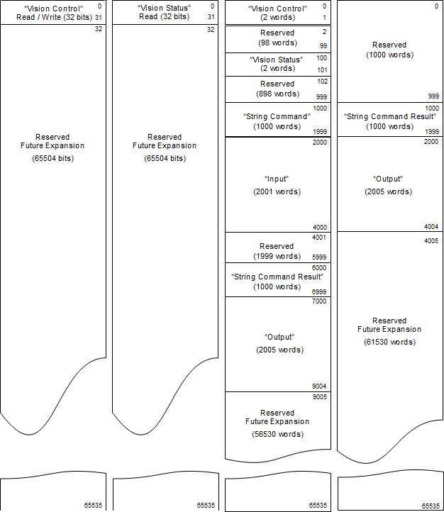
Modbus TCP Address Map
- The Vision Control Block, Vision Status Block, Output Block and String Command Result Block are mapped to two separate locations. The reason for this double-mapping is that some PLCs can only access the Holding Register portion of the address space (for example, they only support function codes 3 and 16). The double-mapping allows those PLCs that can only access Holding Registers to successfully access all signals and data. However, PLCs that support the full function code set can access these blocks in their optimal address map locations. Please note that you can access either the optimal block location or the Holding Register location, but not both.
- Natively, the Modbus TCP protocol uses zero based offsets for addressing. The address map diagram below shows the block locations using zero based offset. If your PLC uses Schneider form addressing, simply add the zero based offsets shown in the address map to the base Schneider address. For example, to access the Input Block using Schneider form addressing, you must add the Input Block offset (2000) to the Schneider base address for Holding Registers (400000). Therefore, in Schneider form, the Input Block starts at 402000.
Modbus TCP supports four distinct address spaces. There are 2 bit address space and 2 word (16-bit) address spaces.
- Coil: Bit type address space. Output from PLC, input to vision system
- Discrete Input: Bit type address space. Input to PLC, output from vision system
- Holding Register: Word type address space. Both Input & Output from vision system
- Input Register: Word type address space. Input to PLC, output from vision system
| Block Name | Address Space | Offset | Schneider Form Addressing | Quantity |
|---|---|---|---|---|
| Vision Control | Coil | 0 | 000000 – 000031 | 1 – 32 |
| Holding Register | 0 | 400000 – 400001 | 1 – 2 | |
| Vision Status | Discrete Input | 0 | 100000 – 100031 | 1 – 32 |
| Holding Register | 100 | 400100 – 400101 | 1 – 2 | |
| Input | Holding Register | 2000 | 402000 – 404000 | 1 – 2001 |
| Output | Holding Register | 7000 | 407000 – 409005 | 1 – 2006 |
| Input Register | 2000 | 302000 – 304005 | 1 – 2006 | |
| String Command | Holding Register | 1000 | 401000 – 401999 | 1 – 1000 |
| String Command Result | Input Register | 1000 | 301000 – 301999 | 1 – 1000 |
| Holding Register | 6000 | 406000 – 406999 | 1 – 1000 |
| Address (000000)
Coil Read / Write (0x01 ,0x05, 0x0F) |
Address (100000)
Discrete Input Read (0x02) |
Address (400000)
Holding Read / Write (0x03 ,0x10) |
Address (300000)
Input Register Read (0x04) |
|---|---|---|---|
|
|||